参数资料
| 型号: | PIC16CR77T-I/PT |
| 厂商: | Microchip Technology |
| 文件页数: | 59/172页 |
| 文件大小: | 0K |
| 描述: | IC PIC MCU 8KX14 44TQFP |
| 标准包装: | 1,200 |
| 系列: | PIC® 16C |
| 核心处理器: | PIC |
| 芯体尺寸: | 8-位 |
| 速度: | 20MHz |
| 连通性: | I²C,SPI,UART/USART |
| 外围设备: | 欠压检测/复位,POR,PWM,WDT |
| 输入/输出数: | 33 |
| 程序存储器容量: | 14KB(8K x 14) |
| 程序存储器类型: | ROM |
| RAM 容量: | 368 x 8 |
| 电压 - 电源 (Vcc/Vdd): | 2 V ~ 5.5 V |
| 数据转换器: | A/D 8x8b |
| 振荡器型: | 内部 |
| 工作温度: | -40°C ~ 85°C |
| 封装/外壳: | 44-TQFP |
| 包装: | 带卷 (TR) |
第1页第2页第3页第4页第5页第6页第7页第8页第9页第10页第11页第12页第13页第14页第15页第16页第17页第18页第19页第20页第21页第22页第23页第24页第25页第26页第27页第28页第29页第30页第31页第32页第33页第34页第35页第36页第37页第38页第39页第40页第41页第42页第43页第44页第45页第46页第47页第48页第49页第50页第51页第52页第53页第54页第55页第56页第57页第58页当前第59页第60页第61页第62页第63页第64页第65页第66页第67页第68页第69页第70页第71页第72页第73页第74页第75页第76页第77页第78页第79页第80页第81页第82页第83页第84页第85页第86页第87页第88页第89页第90页第91页第92页第93页第94页第95页第96页第97页第98页第99页第100页第101页第102页第103页第104页第105页第106页第107页第108页第109页第110页第111页第112页第113页第114页第115页第116页第117页第118页第119页第120页第121页第122页第123页第124页第125页第126页第127页第128页第129页第130页第131页第132页第133页第134页第135页第136页第137页第138页第139页第140页第141页第142页第143页第144页第145页第146页第147页第148页第149页第150页第151页第152页第153页第154页第155页第156页第157页第158页第159页第160页第161页第162页第163页第164页第165页第166页第167页第168页第169页第170页第171页第172页
2007 Microchip Technology Inc.
DS39599G-page 149
PIC18F2220/2320/4220/4320
16.4.4
PROGRAMMABLE DEAD-BAND
DELAY
In half-bridge applications, where all power switches
are modulated at the PWM frequency at all times, the
power switches normally require more time to turn off
than to turn on. If both the upper and lower power
switches are switched at the same time (one turned on
and the other turned off), both switches may be on for
a short period of time until one switch completely turns
off. During this brief interval, a very high current (shoot-
through current) may flow through both power
switches, shorting the bridge supply. To avoid this
potentially destructive shoot-through current from flow-
ing during switching, turning on either of the power
switches is normally delayed to allow the other switch
to completely turn off.
In the Half-Bridge Output mode, a digitally program-
mable dead band delay is available to avoid shoot-
through current from destroying the bridge power
switches. The delay occurs at the signal transition from
the non-active state to the active state. See Figure 16-4
for illustration. The lower seven bits of the PWM1CON
register (Register 16-2) set the delay period in terms of
microcontroller instruction cycles (TCY or 4 TOSC).
16.4.5
ENHANCED PWM
AUTO-SHUTDOWN
When the ECCP is programmed for any of the
enhanced PWM modes, the active output pins may be
configured for auto-shutdown. Auto-shutdown immedi-
ately places the enhanced PWM output pins into a
defined shutdown state when a shutdown event
occurs.
A shutdown event can be caused by either of the two
comparator modules or the INT0 pin (or any combina-
tion of these three sources). The comparators may be
used to monitor a voltage input proportional to a current
being monitored in the bridge circuit. If the voltage
exceeds a threshold, the comparator switches state
and triggers a shutdown. Alternatively, a digital signal
on the INT0 pin can also trigger a shutdown. The auto-
shutdown feature can be disabled by not selecting any
auto-shutdown sources. The auto-shutdown sources to
be used are selected using the ECCPAS2:ECCPAS0
bits (ECCPAS<6:4>).
When a shutdown occurs, the output pins are asyn-
chronously placed in their shutdown states, specified
by the PSSAC1:PSSAC0 and PSSBD1:PSSBD0 bits
(ECCPAS<3:0>). Each pin pair (P1A/P1C and P1B/
P1D) may be set to drive high, drive low or be tri-stated
(not driving). The ECCPASE bit (ECCPAS<7>) is also
set to hold the enhanced PWM outputs in their
shutdown states.
The ECCPASE bit is set by hardware when a shutdown
event occurs. If automatic restarts are not enabled, the
ECCPASE bit is cleared by firmware when the cause of
the shutdown clears. If automatic restarts are enabled,
the ECCPASE bit is automatically cleared when the
cause of the auto-shutdown has cleared.
If the ECCPASE bit is set when a PWM period begins,
the PWM outputs remain in their shutdown state for that
entire PWM period. When the ECCPASE bit is cleared,
the PWM outputs will return to normal operation at the
beginning of the next PWM period.
Note:
Writing to the ECCPASE bit is disabled
while a shutdown condition is active.
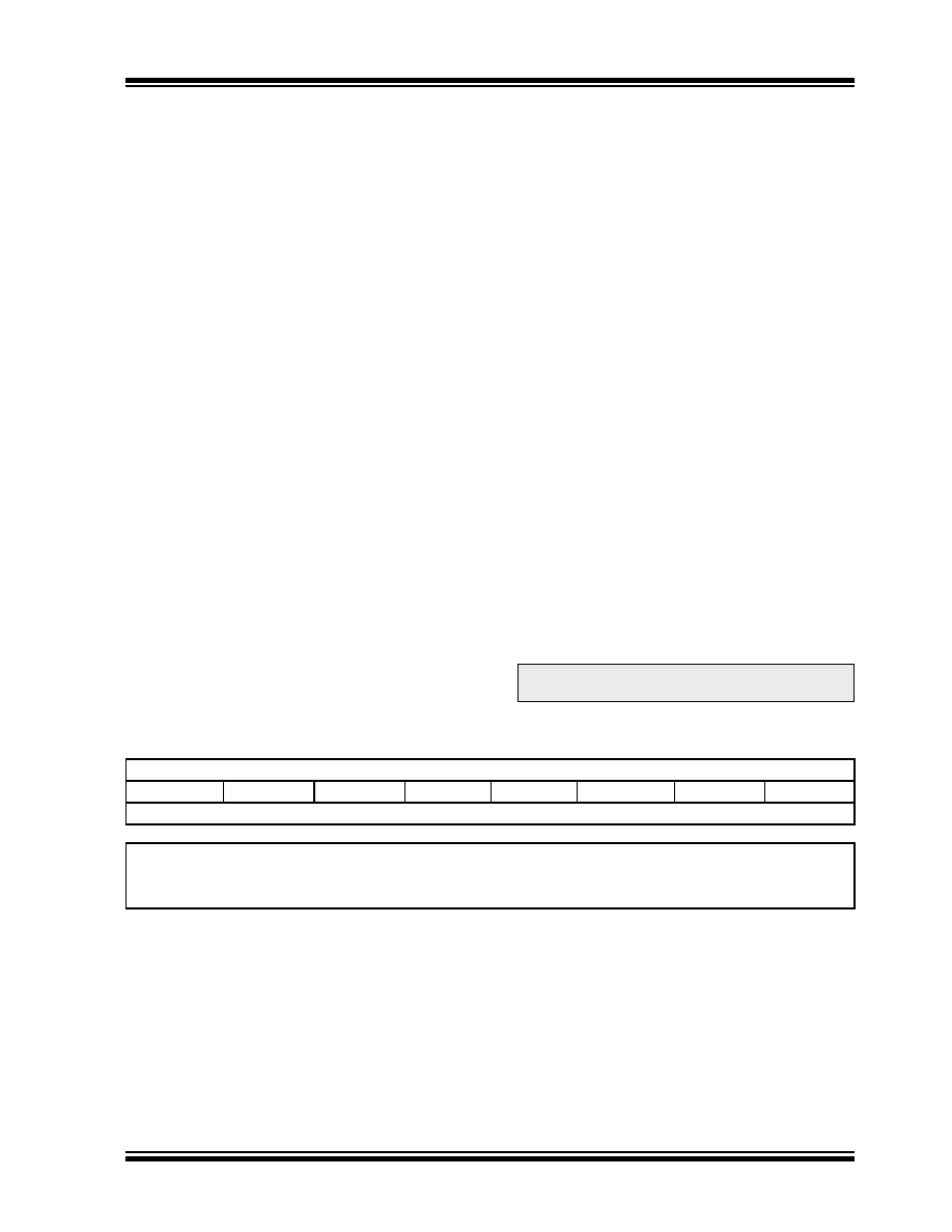
REGISTER 16-2:
PWM1CON: PWM CONFIGURATION REGISTER
R/W-0
PRSEN
PDC6
PDC5
PDC4
PDC3
PDC2
PDC1
PDC0
bit 7
bit 0
Legend:
R = Readable bit
W = Writable bit
U = Unimplemented bit, read as ‘0’
-n = Value at POR
‘1’ = Bit is set
‘0’ = Bit is cleared
x = Bit is unknown
bit 7
PRSEN: PWM Restart Enable bit
1 = Upon auto-shutdown, the ECCPASE bit clears automatically once the shutdown event goes away;
the PWM restarts automatically
0 = Upon auto-shutdown, ECCPASE must be cleared in software to restart the PWM
bit 6-0
PDC6:PDC0: PWM Delay Count bits
Delay time, in number of FOSC/4 (4 * TOSC) cycles, between the scheduled time when a PWM signal
should transition to active and the actual time it transitions active.
相关PDF资料 |
PDF描述 |
|---|---|
| PIC16F1503-I/SL | MCU 8BIT 3.5KB FLASH 14SOIC |
| PIC16F1507-I/SS | IC MCU 8BIT 3.5KB FLASH 20SSOP |
| PIC16F1513-I/MV | IC MCU 8BIT 7KB FLASH 28-UQFN |
| PIC16F1829-I/P | MCU PIC 14K FLASH 1K RAM 20DIP |
| PIC16F1937-I/P | IC PIC MCU FLASH 512KX14 40-PDIP |
相关代理商/技术参数 |
参数描述 |
|---|---|
| PIC16CR83T-04/SO023 | 制造商:Microchip Technology Inc 功能描述: |
| PIC16F | 制造商:Microchip Technology Inc 功能描述:Microchip PIC16F677-I/P Microcontroller |
| PIC16F1454-E/ML | 制造商:Microchip Technology Inc 功能描述:7 KB FLASH, 512 BYTES RAM, 48 MHZ INT. OSC, 12 I/0, ENHANCED - Rail/Tube 制造商:Microchip Technology Inc 功能描述:IC MCU 8BIT 7KB FLASH 16QFN |
| PIC16F1454-E/P | 制造商:Microchip Technology Inc 功能描述:7 KB FLASH, 512 BYTES RAM, 48 MHZ INT. OSC, 12 I/0, ENHANCED - Rail/Tube 制造商:Microchip Technology Inc 功能描述:IC MCU 8BIT 7KB FLASH 14PDIP |
| PIC16F1454-E/SL | 制造商:Microchip Technology Inc 功能描述:7 KB FLASH, 512 BYTES RAM, 48 MHZ INT. OSC, 12 I/0, ENHANCED - Rail/Tube 制造商:Microchip Technology Inc 功能描述:IC MCU 8BIT 7KB FLASH 14SOIC |
发布紧急采购,3分钟左右您将得到回复。