- 您现在的位置:买卖IC网 > PDF目录3821 > PIC16F877A-I/L (Microchip Technology)IC MCU FLASH 8KX14 EE 44PLCC PDF资料下载
参数资料
| 型号: | PIC16F877A-I/L |
| 厂商: | Microchip Technology |
| 文件页数: | 134/234页 |
| 文件大小: | 0K |
| 描述: | IC MCU FLASH 8KX14 EE 44PLCC |
| 产品培训模块: | Asynchronous Stimulus 8-bit PIC® Microcontroller Portfolio |
| 标准包装: | 27 |
| 系列: | PIC® 16F |
| 核心处理器: | PIC |
| 芯体尺寸: | 8-位 |
| 速度: | 20MHz |
| 连通性: | I²C,SPI,UART/USART |
| 外围设备: | 欠压检测/复位,POR,PWM,WDT |
| 输入/输出数: | 33 |
| 程序存储器容量: | 14KB(8K x 14) |
| 程序存储器类型: | 闪存 |
| EEPROM 大小: | 256 x 8 |
| RAM 容量: | 368 x 8 |
| 电压 - 电源 (Vcc/Vdd): | 4 V ~ 5.5 V |
| 数据转换器: | A/D 8x10b |
| 振荡器型: | 外部 |
| 工作温度: | -40°C ~ 85°C |
| 封装/外壳: | 44-LCC(J 形引线) |
| 包装: | 管件 |
| 产品目录页面: | 641 (CN2011-ZH PDF) |
| 配用: | AC164309-ND - MODULE SKT FOR PM3 44PLCC 444-1001-ND - DEMO BOARD FOR PICMICRO MCU 309-1040-ND - ADAPTER 44-PLCC ZIF TO 40-DIP 309-1039-ND - ADAPTER 44-PLCC TO 40-DIP |
| 其它名称: | PIC16F877AI/L |
第1页第2页第3页第4页第5页第6页第7页第8页第9页第10页第11页第12页第13页第14页第15页第16页第17页第18页第19页第20页第21页第22页第23页第24页第25页第26页第27页第28页第29页第30页第31页第32页第33页第34页第35页第36页第37页第38页第39页第40页第41页第42页第43页第44页第45页第46页第47页第48页第49页第50页第51页第52页第53页第54页第55页第56页第57页第58页第59页第60页第61页第62页第63页第64页第65页第66页第67页第68页第69页第70页第71页第72页第73页第74页第75页第76页第77页第78页第79页第80页第81页第82页第83页第84页第85页第86页第87页第88页第89页第90页第91页第92页第93页第94页第95页第96页第97页第98页第99页第100页第101页第102页第103页第104页第105页第106页第107页第108页第109页第110页第111页第112页第113页第114页第115页第116页第117页第118页第119页第120页第121页第122页第123页第124页第125页第126页第127页第128页第129页第130页第131页第132页第133页当前第134页第135页第136页第137页第138页第139页第140页第141页第142页第143页第144页第145页第146页第147页第148页第149页第150页第151页第152页第153页第154页第155页第156页第157页第158页第159页第160页第161页第162页第163页第164页第165页第166页第167页第168页第169页第170页第171页第172页第173页第174页第175页第176页第177页第178页第179页第180页第181页第182页第183页第184页第185页第186页第187页第188页第189页第190页第191页第192页第193页第194页第195页第196页第197页第198页第199页第200页第201页第202页第203页第204页第205页第206页第207页第208页第209页第210页第211页第212页第213页第214页第215页第216页第217页第218页第219页第220页第221页第222页第223页第224页第225页第226页第227页第228页第229页第230页第231页第232页第233页第234页
2008 Microchip Technology Inc.
DS39626E-page 217
PIC18F2525/2620/4525/4620
18.3
EUSART Synchronous
Master Mode
The Synchronous Master mode is entered by setting
the CSRC bit (TXSTA<7>). In this mode, the data is
transmitted in a half-duplex manner (i.e., transmission
and reception do not occur at the same time). When
transmitting data, the reception is inhibited and vice
versa. Synchronous mode is entered by setting bit,
SYNC (TXSTA<4>). In addition, enable bit, SPEN
(RCSTA<7>), is set in order to configure the TX and RX
pins to CK (clock) and DT (data) lines, respectively.
The Master mode indicates that the processor
transmits the master clock on the CK line. Clock
polarity
is
selected
with
the
TXCKP
bit
(BAUDCON<4>); setting TXCKP sets the Idle state on
CK as high, while clearing the bit sets the Idle state as
low. This option is provided to support Microwire
devices with this module.
18.3.1
EUSART SYNCHRONOUS MASTER
TRANSMISSION
The EUSART transmitter block diagram is shown in
Figure 18-3. The heart of the transmitter is the Transmit
(Serial) Shift Register (TSR). The Shift register obtains
its data from the Read/Write Transmit Buffer register,
TXREG. The TXREG register is loaded with data in
software. The TSR register is not loaded until the last
bit has been transmitted from the previous load. As
soon as the last bit is transmitted, the TSR is loaded
with new data from the TXREG (if available).
Once the TXREG register transfers the data to the TSR
register (occurs in one TCY), the TXREG is empty and
the TXIF flag bit (PIR1<4>) is set. The interrupt can be
enabled or disabled by setting or clearing the interrupt
enable bit, TXIE (PIE1<4>). TXIF is set regardless of
the state of enable bit, TXIE; it cannot be cleared in
software. It will reset only when new data is loaded into
the TXREG register.
While flag bit, TXIF, indicates the status of the TXREG
register, another bit, TRMT (TXSTA<1>), shows the
status of the TSR register. TRMT is a read-only bit which
is set when the TSR is empty. No interrupt logic is tied to
this bit so the user has to poll this bit in order to deter-
mine if the TSR register is empty. The TSR is not
mapped in data memory so it is not available to the user.
To set up a Synchronous Master Transmission:
1.
Initialize the SPBRGH:SPBRG registers for the
appropriate baud rate. Set or clear the BRG16
bit, as required, to achieve the desired baud rate.
2.
Enable the synchronous master serial port by
setting bits, SYNC, SPEN and CSRC.
3.
If interrupts are desired, set enable bit, TXIE.
4.
If 9-bit transmission is desired, set bit, TX9.
5.
Enable the transmission by setting bit, TXEN.
6.
If 9-bit transmission is selected, the ninth bit
should be loaded in bit, TX9D.
7.
Start transmission by loading data to the TXREG
register.
8.
If using interrupts, ensure that the GIE and PEIE
bits in the INTCON register (INTCON<7:6>) are
set.
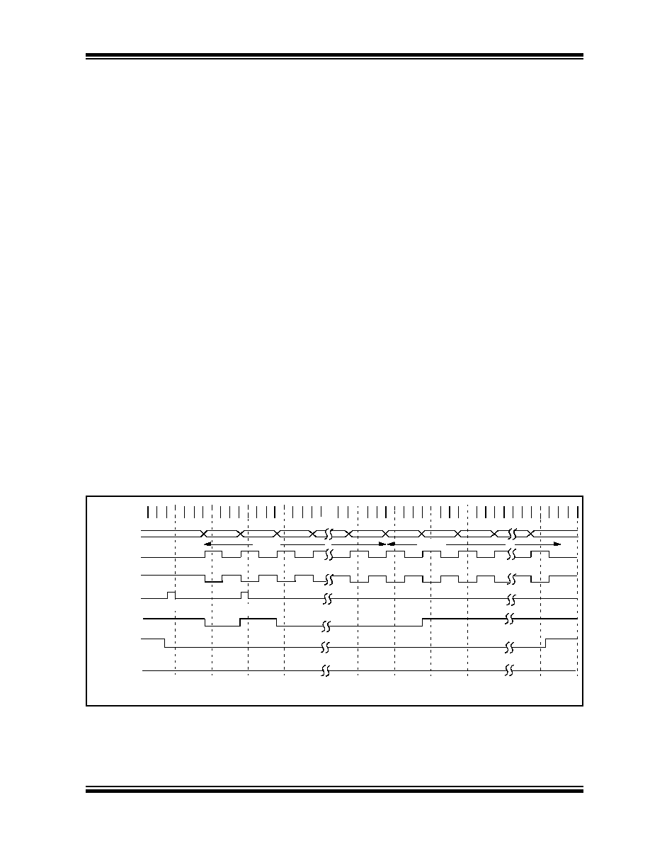
FIGURE 18-11:
SYNCHRONOUS TRANSMISSION
bit 0
bit 1
bit 7
Word 1
Q1 Q2 Q3Q4 Q1 Q2 Q3 Q4 Q1 Q2 Q3 Q4 Q1Q2 Q3 Q4 Q1Q2 Q3 Q4
Q3 Q4 Q1 Q2 Q3 Q4 Q1Q2 Q3 Q4 Q1 Q2 Q3 Q4 Q1 Q2 Q3 Q4 Q1 Q2 Q3 Q4 Q1 Q2 Q3 Q4
bit 2
bit 0
bit 1
bit 7
RC7/RX/DT
RC6/TX/CK pin
Write to
TXREG Reg
TXIF bit
(Interrupt Flag)
TXEN bit ‘1’
‘1’
Word 2
TRMT bit
Write Word 1
Write Word 2
Note:
Sync Master mode, SPBRG = 0, continuous transmission of two 8-bit words.
RC6/TX/CK pin
(TXCKP = 0)
(TXCKP = 1)
相关PDF资料 |
PDF描述 |
|---|---|
| DSPIC33FJ64MC804-E/PT | IC DSPIC MCU/DSP 64K 44-TQFP |
| PIC18LF2480-I/ML | IC PIC MCU FLASH 8KX16 28QFN |
| PIC24HJ128GP504-E/PT | IC PIC MCU FLASH 128K 44-TQFP |
| DSPIC33FJ128GP310-I/PT | IC DSPIC MCU/DSP 128K 100TQFP |
| PIC16C67-04/P | IC MCU OTP 8KX14 PWM 40DIP |
相关代理商/技术参数 |
参数描述 |
|---|---|
| PIC16F877AIP | 制造商:Microchip Technology Inc 功能描述: |
| PIC16F877AIPT | 制造商:Microchip Technology Inc 功能描述: |
| PIC16F877AT-E/ML | 功能描述:8位微控制器 -MCU 20MHz 8K Flash RoHS:否 制造商:Silicon Labs 核心:8051 处理器系列:C8051F39x 数据总线宽度:8 bit 最大时钟频率:50 MHz 程序存储器大小:16 KB 数据 RAM 大小:1 KB 片上 ADC:Yes 工作电源电压:1.8 V to 3.6 V 工作温度范围:- 40 C to + 105 C 封装 / 箱体:QFN-20 安装风格:SMD/SMT |
| PIC16F877AT-E/PT | 功能描述:8位微控制器 -MCU 20MHz 8K Flash RoHS:否 制造商:Silicon Labs 核心:8051 处理器系列:C8051F39x 数据总线宽度:8 bit 最大时钟频率:50 MHz 程序存储器大小:16 KB 数据 RAM 大小:1 KB 片上 ADC:Yes 工作电源电压:1.8 V to 3.6 V 工作温度范围:- 40 C to + 105 C 封装 / 箱体:QFN-20 安装风格:SMD/SMT |
| PIC16F877AT-I/L | 功能描述:8位微控制器 -MCU 14KB 368 RAM 33 I/O RoHS:否 制造商:Silicon Labs 核心:8051 处理器系列:C8051F39x 数据总线宽度:8 bit 最大时钟频率:50 MHz 程序存储器大小:16 KB 数据 RAM 大小:1 KB 片上 ADC:Yes 工作电源电压:1.8 V to 3.6 V 工作温度范围:- 40 C to + 105 C 封装 / 箱体:QFN-20 安装风格:SMD/SMT |
发布紧急采购,3分钟左右您将得到回复。