- 您现在的位置:买卖IC网 > PDF目录11532 > PIC16LC712-04/SS (Microchip Technology)IC MCU OTP 1KX14 A/D PWM 20SSOP PDF资料下载
参数资料
| 型号: | PIC16LC712-04/SS |
| 厂商: | Microchip Technology |
| 文件页数: | 60/106页 |
| 文件大小: | 0K |
| 描述: | IC MCU OTP 1KX14 A/D PWM 20SSOP |
| 产品培训模块: | Asynchronous Stimulus |
| 标准包装: | 67 |
| 系列: | PIC® 16C |
| 核心处理器: | PIC |
| 芯体尺寸: | 8-位 |
| 速度: | 4MHz |
| 外围设备: | 欠压检测/复位,POR,PWM,WDT |
| 输入/输出数: | 13 |
| 程序存储器容量: | 1.75KB(1K x 14) |
| 程序存储器类型: | OTP |
| RAM 容量: | 128 x 8 |
| 电压 - 电源 (Vcc/Vdd): | 2.5 V ~ 5.5 V |
| 数据转换器: | A/D 4x8b |
| 振荡器型: | 外部 |
| 工作温度: | 0°C ~ 70°C |
| 封装/外壳: | 20-SSOP(0.209",5.30mm 宽) |
| 包装: | 管件 |
第1页第2页第3页第4页第5页第6页第7页第8页第9页第10页第11页第12页第13页第14页第15页第16页第17页第18页第19页第20页第21页第22页第23页第24页第25页第26页第27页第28页第29页第30页第31页第32页第33页第34页第35页第36页第37页第38页第39页第40页第41页第42页第43页第44页第45页第46页第47页第48页第49页第50页第51页第52页第53页第54页第55页第56页第57页第58页第59页当前第60页第61页第62页第63页第64页第65页第66页第67页第68页第69页第70页第71页第72页第73页第74页第75页第76页第77页第78页第79页第80页第81页第82页第83页第84页第85页第86页第87页第88页第89页第90页第91页第92页第93页第94页第95页第96页第97页第98页第99页第100页第101页第102页第103页第104页第105页第106页
2005 Microchip Technology Inc.
DS41106B-page 55
PIC16C712/716
9.4
Power-On Reset (POR)
A Power-on Reset pulse is generated on-chip when
VDD rise is detected (to a level of 1.5V-2.1V). To take
advantage of the POR, just tie the MCLR pin directly (or
through a resistor) to VDD. This will eliminate external
RC components usually needed to create a Power-on
Reset. A maximum rise time for VDD is specified
(parameter D004). For a slow rise time, see Figure 9-5.
When the device starts normal operation (exits the
Reset condition), device operating parameters (volt-
age, frequency, temperature,...) must be met to ensure
operation. If these conditions are not met, the device
must be held in Reset until the operating conditions are
met. Brown-out Reset may be used to meet the start-
up conditions.
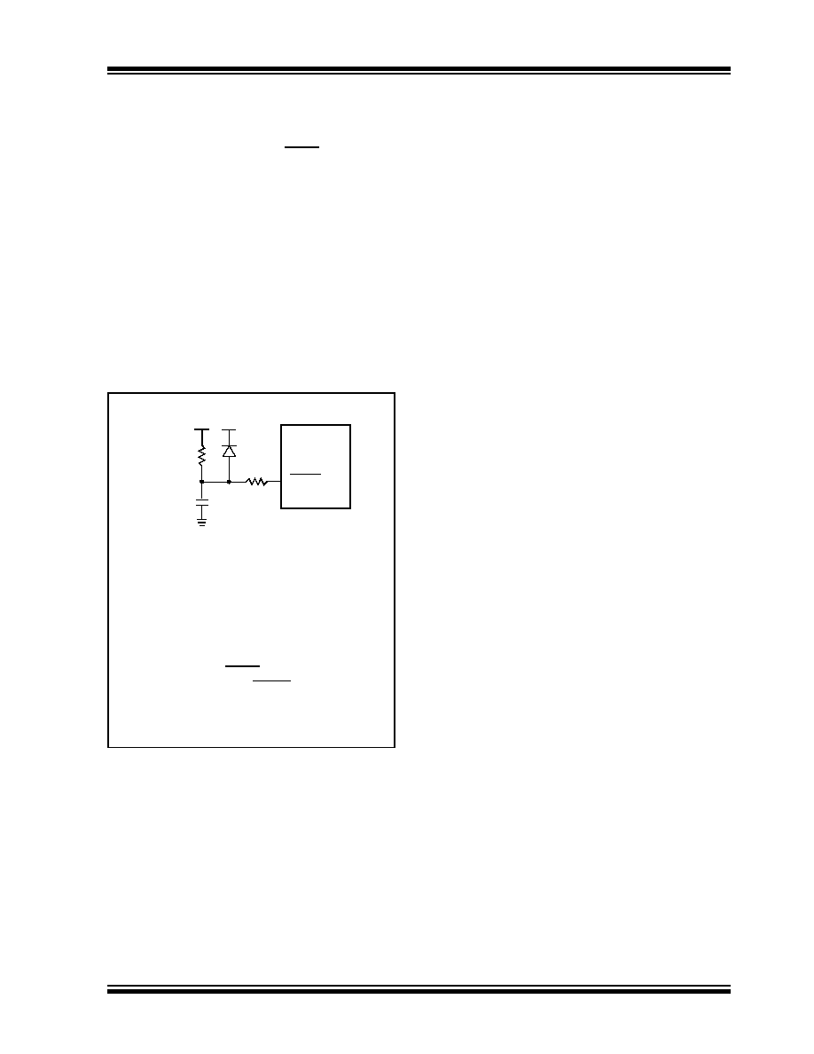
FIGURE 9-5:
EXTERNAL POWER-ON
RESET CIRCUIT (FOR
SLOW VDD POWER-UP)
9.5
Power-up Timer (PWRT)
The Power-up Timer provides a fixed nominal time-out
(parameter #33), on power-up only, from the POR. The
Power-up Timer operates on an internal RC oscillator.
The chip is kept in Reset as long as the PWRT is active.
The PWRT’s time delay allows VDD to rise to an
acceptable level. A Configuration bit is provided to
enable/disable the PWRT.
The power-up time delay will vary from chip to chip due
to VDD, temperature, and process variation. See DC
parameters for details.
9.6
Oscillator Start-up Timer (OST)
The Oscillator Start-up Timer (OST) provides a 1024
oscillator cycle (from OSC1 input) delay after the
PWRT delay is over (parameter #32). This ensures that
the crystal oscillator or resonator has started and
stabilized.
The OST time-out is invoked only for XT, LP and HS
modes and only on Power-on Reset or wake-up from
Sleep.
9.7
Brown-Out Reset (BOR)
The PIC16C712/716 members have on-chip Brown-
out Reset circuitry. A Configuration bit, BODEN, can
disable (if clear/programmed) or enable (if set) the
Brown-out Reset circuitry. If VDD falls below 4.0V, refer
to VBOR parameter D005(VBOR) for a time greater than
tion will reset the chip. A Reset is not guaranteed to
occur if VDD falls below 4.0V for less than parameter
(TBOR).
On any Reset (Power-on, Brown-out, Watchdog, etc.)
the chip will remain in Reset until VDD rises above
VBOR. The Power-up Timer will now be invoked and will
keep the chip in Reset an additional 72 ms.
If VDD drops below VBOR while the Power-up Timer is
running, the chip will go back into a Brown-out Reset
and the Power-up Timer will be re-initialized. Once VDD
rises above VBOR, the Power-Up Timer will execute a
72 ms Reset. The Power-up Timer should always be
enabled when Brown-out Reset is enabled. Figure 9-7
shows typical Brown-out situations.
For operations where the desired brown-out voltage is
other than 4V, an external brown-out circuit must be
used. Figure 9-8, 9-9 and 9-10 show examples of
external brown-out protection circuits.
Note 1: External Power-on Reset circuit is
required only if VDD power-up slope is too
slow. The diode D helps discharge the
capacitor quickly when VDD powers down.
2: R < 40 k
Ω is recommended to make sure
that voltage drop across R does not violate
the device’s electrical specification.
3: R1 = 100
Ω to 1 kΩ will limit any current
flowing into MCLR from external capacitor
C in the event of MCLR/VPP pin break-
down due to Electrostatic Discharge
(ESD) or Electrical Overstress (EOS).
C
R1
R
VDD
MCLR
PIC16C7XX
VDD
相关PDF资料 |
PDF描述 |
|---|---|
| VE-BW4-IY-B1 | CONVERTER MOD DC/DC 48V 50W |
| VE-B2Z-IY-B1 | CONVERTER MOD DC/DC 2V 20W |
| PIC16LC712-04I/SO | IC MCU OTP 1KX14 A/D PWM 18SOIC |
| PIC16LC621A-04/SO | IC MCU OTP 1KX14 COMP 18SOIC |
| PIC16C712-20I/P | IC MCU OTP 1KX14 A/D PWM 18DIP |
相关代理商/技术参数 |
参数描述 |
|---|---|
| PIC16LC712T-04/SO | 功能描述:8位微控制器 -MCU 1.75KB 128RAM 13 I/O RoHS:否 制造商:Silicon Labs 核心:8051 处理器系列:C8051F39x 数据总线宽度:8 bit 最大时钟频率:50 MHz 程序存储器大小:16 KB 数据 RAM 大小:1 KB 片上 ADC:Yes 工作电源电压:1.8 V to 3.6 V 工作温度范围:- 40 C to + 105 C 封装 / 箱体:QFN-20 安装风格:SMD/SMT |
| PIC16LC712T-04/SS | 功能描述:8位微控制器 -MCU 1.75KB 128RAM 13 I/O RoHS:否 制造商:Silicon Labs 核心:8051 处理器系列:C8051F39x 数据总线宽度:8 bit 最大时钟频率:50 MHz 程序存储器大小:16 KB 数据 RAM 大小:1 KB 片上 ADC:Yes 工作电源电压:1.8 V to 3.6 V 工作温度范围:- 40 C to + 105 C 封装 / 箱体:QFN-20 安装风格:SMD/SMT |
| PIC16LC712T-04I/SO | 功能描述:8位微控制器 -MCU 1.75KB 128RAM 13 I/O RoHS:否 制造商:Silicon Labs 核心:8051 处理器系列:C8051F39x 数据总线宽度:8 bit 最大时钟频率:50 MHz 程序存储器大小:16 KB 数据 RAM 大小:1 KB 片上 ADC:Yes 工作电源电压:1.8 V to 3.6 V 工作温度范围:- 40 C to + 105 C 封装 / 箱体:QFN-20 安装风格:SMD/SMT |
| PIC16LC712T-04I/SS | 功能描述:8位微控制器 -MCU 1.75KB 128RAM 13 I/O RoHS:否 制造商:Silicon Labs 核心:8051 处理器系列:C8051F39x 数据总线宽度:8 bit 最大时钟频率:50 MHz 程序存储器大小:16 KB 数据 RAM 大小:1 KB 片上 ADC:Yes 工作电源电压:1.8 V to 3.6 V 工作温度范围:- 40 C to + 105 C 封装 / 箱体:QFN-20 安装风格:SMD/SMT |
| PIC16LC715-04/P | 功能描述:8位微控制器 -MCU 3.5KB 128 RAM 13 I/O RoHS:否 制造商:Silicon Labs 核心:8051 处理器系列:C8051F39x 数据总线宽度:8 bit 最大时钟频率:50 MHz 程序存储器大小:16 KB 数据 RAM 大小:1 KB 片上 ADC:Yes 工作电源电压:1.8 V to 3.6 V 工作温度范围:- 40 C to + 105 C 封装 / 箱体:QFN-20 安装风格:SMD/SMT |
发布紧急采购,3分钟左右您将得到回复。