- 您现在的位置:买卖IC网 > PDF目录3878 > PIC18F25J10-I/SP (Microchip Technology)IC PIC MCU FLASH 16KX16 28DIP PDF资料下载
参数资料
| 型号: | PIC18F25J10-I/SP |
| 厂商: | Microchip Technology |
| 文件页数: | 36/80页 |
| 文件大小: | 0K |
| 描述: | IC PIC MCU FLASH 16KX16 28DIP |
| 产品培训模块: | Asynchronous Stimulus PIC18 J Series MCU Overview 8-bit PIC® Microcontroller Portfolio |
| 标准包装: | 15 |
| 系列: | PIC® 18F |
| 核心处理器: | PIC |
| 芯体尺寸: | 8-位 |
| 速度: | 40MHz |
| 连通性: | I²C,SPI,UART/USART |
| 外围设备: | 欠压检测/复位,POR,PWM,WDT |
| 输入/输出数: | 21 |
| 程序存储器容量: | 32KB(16K x 16) |
| 程序存储器类型: | 闪存 |
| RAM 容量: | 1K x 8 |
| 电压 - 电源 (Vcc/Vdd): | 2.7 V ~ 3.6 V |
| 数据转换器: | A/D 10x10b |
| 振荡器型: | 内部 |
| 工作温度: | -40°C ~ 85°C |
| 封装/外壳: | 28-DIP(0.300",7.62mm) |
| 包装: | 管件 |
| 产品目录页面: | 643 (CN2011-ZH PDF) |
| 配用: | AC162074-ND - HEADER INTRFC MPLAB ICD2 44TQFP MA180011-ND - MODULE PLUG-IN 18F25J10 28SOIC AC162067-ND - HEADER INTRFC MPLAB ICD2 40/28P AC164329-ND - MODULE SKT FOR 40DIP 18F45J10 |
第1页第2页第3页第4页第5页第6页第7页第8页第9页第10页第11页第12页第13页第14页第15页第16页第17页第18页第19页第20页第21页第22页第23页第24页第25页第26页第27页第28页第29页第30页第31页第32页第33页第34页第35页当前第36页第37页第38页第39页第40页第41页第42页第43页第44页第45页第46页第47页第48页第49页第50页第51页第52页第53页第54页第55页第56页第57页第58页第59页第60页第61页第62页第63页第64页第65页第66页第67页第68页第69页第70页第71页第72页第73页第74页第75页第76页第77页第78页第79页第80页
PIC16F8X
1998 Microchip Technology Inc.
DS30430C-page 41
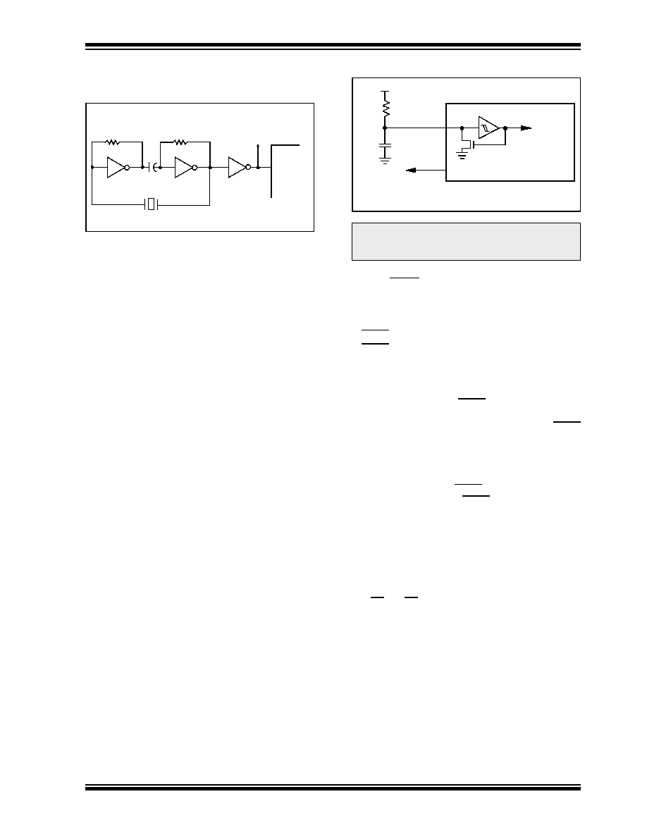
FIGURE 8-6:
EXTERNAL SERIES
RESONANT CRYSTAL
OSCILLATOR CIRCUIT
8.2.4
RC OSCILLATOR
For timing insensitive applications the RC device option
offers additional cost savings. The RC oscillator
frequency is a function of the supply voltage, the
resistor (Rext) values, capacitor (Cext) values, and the
operating temperature. In addition to this, the oscillator
frequency will vary from unit to unit due to normal
process
parameter
variation.
Furthermore,
the
difference in lead frame capacitance between package
types also affects the oscillation frequency, especially
for low Cext values. The user needs to take into
account variation due to tolerance of the external
R and C components. Figure 8-7 shows how an R/C
combination is connected to the PIC16F8X. For Rext
values below 4 k
, the oscillator operation may
become unstable, or stop completely. For very high
Rext values (e.g., 1 M
), the oscillator becomes
sensitive to noise, humidity and leakage. Thus, we
recommend keeping Rext between 5 k
and 100 k.
Although the oscillator will operate with no external
capacitor (Cext = 0 pF), we recommend using values
above 20 pF for noise and stability reasons. With little
or no external capacitance, the oscillation frequency
can vary dramatically due to changes in external
capacitances, such as PCB trace capacitance or
package lead frame capacitance.
See
the
electrical
specification
section
for
RC
frequency variation from part to part due to normal
process variation. The variation is larger for larger R
(since
leakage
current
variation
will
affect
RC
frequency more for large R) and for smaller C (since
variation of input capacitance has a greater affect on
RC frequency).
See the electrical specification section for variation of
oscillator frequency due to VDD for given Rext/Cext
values
as
well
as
frequency
variation
due
to
operating temperature.
The oscillator frequency, divided by 4, is available on
the OSC2/CLKOUT pin, and can be used for test
purposes or to synchronize other logic (see Figure 3-2
for waveform).
FIGURE 8-7:
RC OSCILLATOR MODE
8.3
Reset
The PIC16F8X differentiates between various kinds
of reset:
Power-on Reset (POR)
MCLR reset during normal operation
MCLR reset during SLEEP
WDT Reset (during normal operation)
WDT Wake-up (during SLEEP)
Figure 8-8 shows a simplified block diagram of the
on-chip reset circuit. The MCLR reset path has a noise
filter to ignore small pulses. The electrical specifica-
tions state the pulse width requirements for the MCLR
pin.
Some registers are not affected in any reset condition;
their status is unknown on a POR reset and unchanged
in any other reset. Most other registers are reset to a
“reset state” on POR, MCLR or WDT reset during
normal operation and on MCLR reset during SLEEP.
They are not affected by a WDT reset during SLEEP,
since this reset is viewed as the resumption of normal
operation.
Table 8-3 gives a description of reset conditions for the
program counter (PC) and the STATUS register.
Table 8-4 gives a full description of reset states for all
registers.
The TO and PD bits are set or cleared differently in dif-
ferent reset situations (Section 8.7). These bits are
used in software to determine the nature of the reset.
330 k
74AS04
PIC16FXX
CLKIN
To Other
Devices
XTAL
330 k
74AS04
0.1
F
Note:
When the device oscillator is in RC mode,
do not drive the OSC1 pin with an external
clock or you may damage the device.
OSC2/CLKOUT
Cext
Rext
PIC16FXX
OSC1
Fosc/4
Internal
clock
VDD
VSS
Recommended values:
5 k
≤ Rext ≤ 100 k
Cext > 20pF
相关PDF资料 |
PDF描述 |
|---|---|
| PIC12C672-04/P | IC MCU OTP 2KX14 A/D 8DIP |
| PIC18LF252T-I/SOG | IC MCU FLASH 16KX16 28SOIC |
| PIC18F44J10-I/PT | IC PIC MCU FLASH 8KX16 44TQFP |
| PIC18LF2410T-I/SO | IC MCU FLASH 8KX16 28SOIC |
| PIC12C671-04/P | IC MCU OTP 1KX14 A/D 8DIP |
相关代理商/技术参数 |
参数描述 |
|---|---|
| PIC18F25J10T-I/ML | 功能描述:8位微控制器 -MCU 32 KB FL 1024 RAM RoHS:否 制造商:Silicon Labs 核心:8051 处理器系列:C8051F39x 数据总线宽度:8 bit 最大时钟频率:50 MHz 程序存储器大小:16 KB 数据 RAM 大小:1 KB 片上 ADC:Yes 工作电源电压:1.8 V to 3.6 V 工作温度范围:- 40 C to + 105 C 封装 / 箱体:QFN-20 安装风格:SMD/SMT |
| PIC18F25J10T-I/SO | 功能描述:8位微控制器 -MCU 32 KB FL 1024 RAM RoHS:否 制造商:Silicon Labs 核心:8051 处理器系列:C8051F39x 数据总线宽度:8 bit 最大时钟频率:50 MHz 程序存储器大小:16 KB 数据 RAM 大小:1 KB 片上 ADC:Yes 工作电源电压:1.8 V to 3.6 V 工作温度范围:- 40 C to + 105 C 封装 / 箱体:QFN-20 安装风格:SMD/SMT |
| PIC18F25J10T-I/SS | 功能描述:8位微控制器 -MCU 16 KB FL 1 KB RAM RoHS:否 制造商:Silicon Labs 核心:8051 处理器系列:C8051F39x 数据总线宽度:8 bit 最大时钟频率:50 MHz 程序存储器大小:16 KB 数据 RAM 大小:1 KB 片上 ADC:Yes 工作电源电压:1.8 V to 3.6 V 工作温度范围:- 40 C to + 105 C 封装 / 箱体:QFN-20 安装风格:SMD/SMT |
| PIC18F25J11-I/ML | 功能描述:8位微控制器 -MCU 32KB Flash 4KBRAM 12MIPS nanoWatt RoHS:否 制造商:Silicon Labs 核心:8051 处理器系列:C8051F39x 数据总线宽度:8 bit 最大时钟频率:50 MHz 程序存储器大小:16 KB 数据 RAM 大小:1 KB 片上 ADC:Yes 工作电源电压:1.8 V to 3.6 V 工作温度范围:- 40 C to + 105 C 封装 / 箱体:QFN-20 安装风格:SMD/SMT |
| PIC18F25J11-I/SO | 功能描述:8位微控制器 -MCU 32KB Flash 4KBRAM 12MIPS nanoWatt RoHS:否 制造商:Silicon Labs 核心:8051 处理器系列:C8051F39x 数据总线宽度:8 bit 最大时钟频率:50 MHz 程序存储器大小:16 KB 数据 RAM 大小:1 KB 片上 ADC:Yes 工作电源电压:1.8 V to 3.6 V 工作温度范围:- 40 C to + 105 C 封装 / 箱体:QFN-20 安装风格:SMD/SMT |
发布紧急采购,3分钟左右您将得到回复。