- 您现在的位置:买卖IC网 > PDF目录11273 > PIC18F4220-I/ML (Microchip Technology)IC MCU FLASH 2KX16 EEPROM 44QFN PDF资料下载
参数资料
| 型号: | PIC18F4220-I/ML |
| 厂商: | Microchip Technology |
| 文件页数: | 208/266页 |
| 文件大小: | 0K |
| 描述: | IC MCU FLASH 2KX16 EEPROM 44QFN |
| 产品培训模块: | Asynchronous Stimulus 8-bit PIC® Microcontroller Portfolio |
| 标准包装: | 45 |
| 系列: | PIC® 18F |
| 核心处理器: | PIC |
| 芯体尺寸: | 8-位 |
| 速度: | 40MHz |
| 连通性: | I²C,SPI,UART/USART |
| 外围设备: | 欠压检测/复位,LVD,POR,PWM,WDT |
| 输入/输出数: | 36 |
| 程序存储器容量: | 4KB(2K x 16) |
| 程序存储器类型: | 闪存 |
| EEPROM 大小: | 256 x 8 |
| RAM 容量: | 512 x 8 |
| 电压 - 电源 (Vcc/Vdd): | 4.2 V ~ 5.5 V |
| 数据转换器: | A/D 13x10b |
| 振荡器型: | 内部 |
| 工作温度: | -40°C ~ 85°C |
| 封装/外壳: | 44-VQFN 裸露焊盘 |
| 包装: | 管件 |
| 配用: | XLT44QFN2-ND - SOCKET TRAN ICE 44QFN/40DIP AC164322-ND - MODULE SOCKET MPLAB PM3 28/44QFN 444-1001-ND - DEMO BOARD FOR PICMICRO MCU |
第1页第2页第3页第4页第5页第6页第7页第8页第9页第10页第11页第12页第13页第14页第15页第16页第17页第18页第19页第20页第21页第22页第23页第24页第25页第26页第27页第28页第29页第30页第31页第32页第33页第34页第35页第36页第37页第38页第39页第40页第41页第42页第43页第44页第45页第46页第47页第48页第49页第50页第51页第52页第53页第54页第55页第56页第57页第58页第59页第60页第61页第62页第63页第64页第65页第66页第67页第68页第69页第70页第71页第72页第73页第74页第75页第76页第77页第78页第79页第80页第81页第82页第83页第84页第85页第86页第87页第88页第89页第90页第91页第92页第93页第94页第95页第96页第97页第98页第99页第100页第101页第102页第103页第104页第105页第106页第107页第108页第109页第110页第111页第112页第113页第114页第115页第116页第117页第118页第119页第120页第121页第122页第123页第124页第125页第126页第127页第128页第129页第130页第131页第132页第133页第134页第135页第136页第137页第138页第139页第140页第141页第142页第143页第144页第145页第146页第147页第148页第149页第150页第151页第152页第153页第154页第155页第156页第157页第158页第159页第160页第161页第162页第163页第164页第165页第166页第167页第168页第169页第170页第171页第172页第173页第174页第175页第176页第177页第178页第179页第180页第181页第182页第183页第184页第185页第186页第187页第188页第189页第190页第191页第192页第193页第194页第195页第196页第197页第198页第199页第200页第201页第202页第203页第204页第205页第206页第207页当前第208页第209页第210页第211页第212页第213页第214页第215页第216页第217页第218页第219页第220页第221页第222页第223页第224页第225页第226页第227页第228页第229页第230页第231页第232页第233页第234页第235页第236页第237页第238页第239页第240页第241页第242页第243页第244页第245页第246页第247页第248页第249页第250页第251页第252页第253页第254页第255页第256页第257页第258页第259页第260页第261页第262页第263页第264页第265页第266页
PIC18F2220/2320/4220/4320
DS39599G-page 44
2007 Microchip Technology Inc.
4.1
Power-on Reset (POR)
A Power-on Reset pulse is generated on-chip when
VDD rise is detected. To take advantage of the POR cir-
cuitry, just tie the MCLR pin through a resistor (1k to
10 k
Ω) to VDD. This will eliminate external RC compo-
nents usually needed to create a Power-on Reset
delay. A minimum rise rate for VDD is specified
(parameter D004). For a slow rise time, see Figure 4-2.
When the device starts normal operation (i.e., exits the
Reset condition), device operating parameters (volt-
age, frequency, temperature, etc.) must be met to
ensure operation. If these conditions are not met, the
device must be held in Reset until the operating
conditions are met.
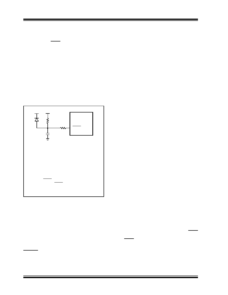
FIGURE 4-2:
EXTERNAL POWER-ON
RESET CIRCUIT (FOR
SLOW VDD POWER-UP)
4.2
Power-up Timer (PWRT)
The Power-up Timer (PWRT) of the PIC18F2X20/4X20
devices is an 11-bit counter, which uses the INTRC
source as the clock input. This yields a count of
2048 x 32
μs = 65.6 ms. While the PWRT is counting,
the device is held in Reset.
The power-up time delay depends on the INTRC clock
and will vary from chip-to-chip due to temperature and
process variation. See DC parameter #33 for details.
The PWRT is enabled by clearing Configuration bit,
PWRTEN.
4.3
Oscillator Start-up Timer (OST)
The Oscillator Start-up Timer (OST) provides a
1024 oscillator cycle (from OSC1 input) delay after the
PWRT delay is over (parameter #33). This ensures that
the crystal oscillator or resonator has started and
stabilized.
The OST time-out is invoked only for XT, LP, HS and
HSPLL modes and only on Power-on Reset, or on exit
from most power-managed modes.
4.4
PLL Lock Time-out
With the PLL enabled in its PLL mode, the time-out
sequence following a Power-on Reset is slightly
different from other oscillator modes. A portion of the
Power-up Timer is used to provide a fixed time-out that
is sufficient for the PLL to lock to the main oscillator fre-
quency. This PLL lock time-out (TPLL) is typically 2 ms
and follows the oscillator start-up time-out.
4.5
Brown-out Reset (BOR)
A Configuration bit, BOREN, can disable (if clear/
programmed) or enable (if set) the Brown-out Reset cir-
cuitry. If VDD falls below VBOR (parameter D005) for
greater than TBOR (parameter #35), the brown-out situ-
ation will reset the chip. A Reset may not occur if VDD
falls below VBOR for less than TBOR. The chip will
remain in Brown-out Reset until VDD rises above VBOR.
If the Power-up Timer is enabled, it will be invoked after
VDD rises above VBOR; it then will keep the chip in
Reset for an additional time delay TPWRT (parameter
#33). If VDD drops below VBOR while the Power-up
Timer is running, the chip will go back into a Brown-out
Reset and the Power-up Timer will be initialized. Once
VDD rises above VBOR, the Power-up Timer will execute
the additional time delay. Enabling BOR Reset does
not automatically enable the PWRT.
4.6
Time-out Sequence
On power-up, the time-out sequence is as follows:
First, after the POR pulse has cleared, PWRT time-out
is invoked (if enabled). Then, the OST is activated. The
total time-out will vary based on oscillator configuration
and the status of the PWRT. For example, in RC mode
with the PWRT disabled, there will be no time-out at all.
Figure 4-7 depict time-out sequences on power-up.
Since the time-outs occur from the POR pulse, if MCLR
is kept low long enough, all time-outs will expire. Bring-
ing MCLR high will begin execution immediately
(Figure 4-5). This is useful for testing purposes or to
synchronize more than one PIC18FXXXX device
operating in parallel.
Table 4-2 shows the Reset conditions for some Special
Function Registers, while Table 4-3 shows the Reset
conditions for all the registers.
Note 1: External
Power-on
Reset
circuit
is
required only if the VDD power-up slope is
too slow. The diode D helps discharge the
capacitor quickly when VDD powers down.
2: R < 40 k
Ω is recommended to make sure
that the voltage drop across R does not
violate the device’s electrical specification.
3: R1
≥ 1 kΩ will limit any current flowing into
MCLR from external capacitor C, in the
event of MCLR/VPP pin breakdown, due to
Electrostatic Discharge (ESD) or Electrical
Overstress (EOS).
C
R1
R
D
VDD
MCLR
PIC18FXXXX
VDD
相关PDF资料 |
PDF描述 |
|---|---|
| VE-20F-IX-F4 | CONVERTER MOD DC/DC 72V 75W |
| VE-20F-IX-F3 | CONVERTER MOD DC/DC 72V 75W |
| PIC16F877-10E/PQ | IC MCU FLASH 8KX14 EE 44-MQFP |
| PIC16LC74A-04/L | IC MCU OTP 4KX14 A/D PWM 44PLCC |
| VE-20F-IX-F2 | CONVERTER MOD DC/DC 72V 75W |
相关代理商/技术参数 |
参数描述 |
|---|---|
| PIC18F4220T-I/ML | 功能描述:8位微控制器 -MCU 4KB 512 RAM 36 I/O RoHS:否 制造商:Silicon Labs 核心:8051 处理器系列:C8051F39x 数据总线宽度:8 bit 最大时钟频率:50 MHz 程序存储器大小:16 KB 数据 RAM 大小:1 KB 片上 ADC:Yes 工作电源电压:1.8 V to 3.6 V 工作温度范围:- 40 C to + 105 C 封装 / 箱体:QFN-20 安装风格:SMD/SMT |
| PIC18F4220T-I/PT | 功能描述:8位微控制器 -MCU 4KB 512 RAM 36 I/O RoHS:否 制造商:Silicon Labs 核心:8051 处理器系列:C8051F39x 数据总线宽度:8 bit 最大时钟频率:50 MHz 程序存储器大小:16 KB 数据 RAM 大小:1 KB 片上 ADC:Yes 工作电源电压:1.8 V to 3.6 V 工作温度范围:- 40 C to + 105 C 封装 / 箱体:QFN-20 安装风格:SMD/SMT |
| PIC18F4221-E/ML | 功能描述:8位微控制器 -MCU 4KB FLSH 512 RAM RoHS:否 制造商:Silicon Labs 核心:8051 处理器系列:C8051F39x 数据总线宽度:8 bit 最大时钟频率:50 MHz 程序存储器大小:16 KB 数据 RAM 大小:1 KB 片上 ADC:Yes 工作电源电压:1.8 V to 3.6 V 工作温度范围:- 40 C to + 105 C 封装 / 箱体:QFN-20 安装风格:SMD/SMT |
| PIC18F4221-E/P | 功能描述:8位微控制器 -MCU 4KB FLSH 512 RAM RoHS:否 制造商:Silicon Labs 核心:8051 处理器系列:C8051F39x 数据总线宽度:8 bit 最大时钟频率:50 MHz 程序存储器大小:16 KB 数据 RAM 大小:1 KB 片上 ADC:Yes 工作电源电压:1.8 V to 3.6 V 工作温度范围:- 40 C to + 105 C 封装 / 箱体:QFN-20 安装风格:SMD/SMT |
| PIC18F4221-E/PT | 功能描述:8位微控制器 -MCU 4KB FLSH 512 RAM RoHS:否 制造商:Silicon Labs 核心:8051 处理器系列:C8051F39x 数据总线宽度:8 bit 最大时钟频率:50 MHz 程序存储器大小:16 KB 数据 RAM 大小:1 KB 片上 ADC:Yes 工作电源电压:1.8 V to 3.6 V 工作温度范围:- 40 C to + 105 C 封装 / 箱体:QFN-20 安装风格:SMD/SMT |
发布紧急采购,3分钟左右您将得到回复。