- 您现在的位置:买卖IC网 > PDF目录69047 > PKB4418PIPOANBM (ERICSSON POWER MODULES AB) 1-OUTPUT 45 W DC-DC REG PWR SUPPLY MODULE PDF资料下载
参数资料
| 型号: | PKB4418PIPOANBM |
| 厂商: | ERICSSON POWER MODULES AB |
| 元件分类: | 电源模块 |
| 英文描述: | 1-OUTPUT 45 W DC-DC REG PWR SUPPLY MODULE |
| 文件页数: | 10/23页 |
| 文件大小: | 367K |
| 代理商: | PKB4418PIPOANBM |
18
EN/LZT 146 033 R1D Ericsson Power Modules, June 2004
PKB 4000 Datasheet
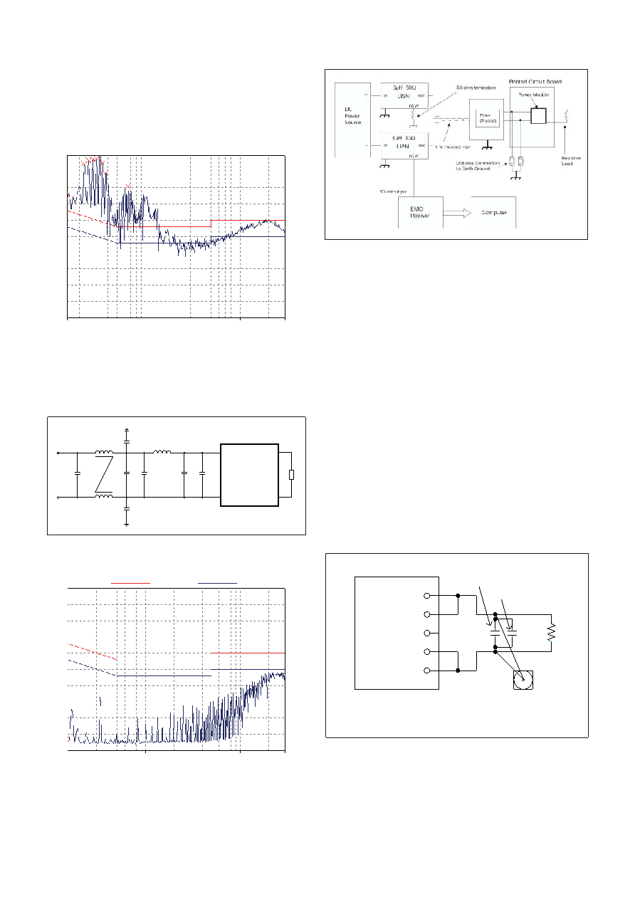
EMC Specication
The conducted EMI measurement was performed using a
module placed directly on the test bench.
The fundamental switching frequency is 160kHz for
PKB 4610 PINB @ VI = 53V, IO = (0.1...1.0) x IOmax.
External lter (class B)
Required external input lter in order to meet class B in
EN 55022, CISPR 22 and FCC part 15J.
The capacitors used are of ceramic type.
Test set-up.
L2
768 H
L1
5.6 H
C6
3.9 nF
C3
47 F
C4
0.68 F
C2
0.68 F
C1
47 F
C7
3.9 nF
C5
0.68 F
DC/DC
R
Layout Recommendation
The radiated EMI performance of the DC/DC converter will be
optimised by including a ground plane in the PCB area under
the DC/DC converter. This approach will return switching
noise to ground as directly as possible, with improvements to
both emissions and susceptibility. If one ground trace is used,
it should be connected to the input return. Alternatively, two
ground traces may be used, with the trace under the input side
of the DC/DC converter connected to the input return and the
trace under the output side of the DC/DC converter connected
to the output return. Make sure to use appropriate safety
isolation spacing between these two return traces. The use of
two traces as described will provide the capability of routing
the input noise and output noise back to their respective
returns.
100
90
80
70
60
50
40
30
20
10
0
0.15
1.0
10.0
30.0
MHz
22B_QP
22B_AV
dBV
100
90
80
70
60
50
40
30
20
10
0
0.15
1.0
10.0
30.0
MHz
22B_QP
22B_AV
dBV
PKB 4610 PINB without lter.
PKB 4610 PINB with lter.
Conducted EMI Input terminal value (typ)
BNC
Connector
to Scope
Ceramic
Capacitor
+Vout
+Sense
Trim
-Sense
-Vout
Load
Tantalum
Capacitor
* Conductor from Vout to capacitors = 50mm [1.97in]
+
0.1uF
10uF
Output ripple and noise test setup
Output ripple and noise
The circuit below has been used for the ripple and noise meas-
urements on the PKB 4000 Series DC/DC converters.
相关PDF资料 |
PDF描述 |
|---|---|
| PKB4418PIPOANBMLA | 1-OUTPUT 45 W DC-DC REG PWR SUPPLY MODULE |
| PKB4318PIPOBNBLA | 1-OUTPUT 36 W DC-DC REG PWR SUPPLY MODULE |
| PKB4418PIPOANBLA | 1-OUTPUT 45 W DC-DC REG PWR SUPPLY MODULE |
| PKB4318PIPOBNBMLA | 1-OUTPUT 36 W DC-DC REG PWR SUPPLY MODULE |
| PKB4318PIPOBNBM | 1-OUTPUT 36 W DC-DC REG PWR SUPPLY MODULE |
相关代理商/技术参数 |
参数描述 |
|---|---|
| PKB4418SIOANB | 制造商:Ericsson 功能描述:- Trays |
| PKB4513PINBLC | 功能描述:DC/DC 开关控制器 DC/DC CONV in 36-60V output 12V 4A 48W RoHS:否 制造商:Texas Instruments 输入电压:6 V to 100 V 开关频率: 输出电压:1.215 V to 80 V 输出电流:3.5 A 输出端数量:1 最大工作温度:+ 125 C 安装风格: 封装 / 箱体:CPAK |
| PKB4513PINBOVL | 制造商:Ericsson 功能描述: |
| PKB4513PINBOVLC | 制造商:Ericsson 功能描述:- Trays |
| PKB4519PINB | 制造商:ERIC 功能描述: |
发布紧急采购,3分钟左右您将得到回复。