- 您现在的位置:买卖IC网 > PDF目录98052 > PKB4619PIPNBP (ERICSSON POWER MODULES AB) 1-OUTPUT 62.5 W DC-DC REG PWR SUPPLY MODULE PDF资料下载
参数资料
| 型号: | PKB4619PIPNBP |
| 厂商: | ERICSSON POWER MODULES AB |
| 元件分类: | 电源模块 |
| 英文描述: | 1-OUTPUT 62.5 W DC-DC REG PWR SUPPLY MODULE |
| 封装: | 58 X 19.94 MM, 7.62 MM HEIGHT, LOW PROFILE, EIGHTH BRIK PACKAGE-8 |
| 文件页数: | 5/12页 |
| 文件大小: | 233K |
| 代理商: | PKB4619PIPNBP |
2
PKB 4000
EN/LZT 146 033 R1A Ericsson Power Modules, October 2003
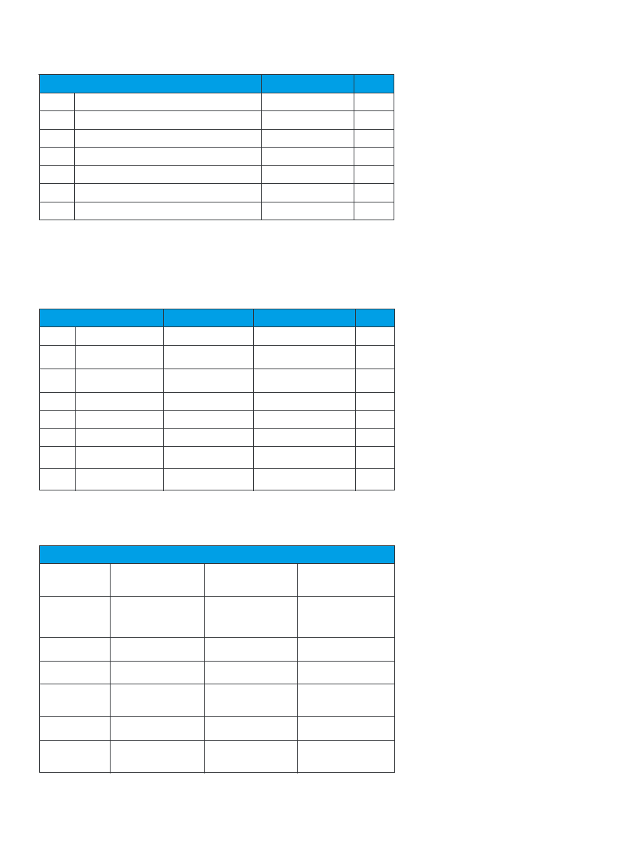
Characteristics
Conditions
min
typ
max
Unit
VI
Input voltage range
36
75
Vdc
VIoff
Turn-off input voltage
Ramping from higher
voltage
30
33.5
35
Vdc
VIon
Turn-on input voltage
Ramping from lower
voltage
32
34.5
36
Vdc
CI
Input capacitance
2.18
F
IIac
Reected ripple current
5 Hz to 20 MHz
10
mAp-p
PII
Input idling power
Io= 0, VI = 53 V
1.6
W
PRC
Input standby power
(turned off with RC)
VI = 53 V, RC open
0.055
W
VTRIM
Max input voltage on
trim pin
6.6
Vdc
Characteristics
min
max
Unit
TPcb
Maximum Operating Pcb Temperature
-40
+110
C
TS
Storage temperature
-55
+125
C
VI
Input voltage
-0.5
+80
Vdc
VISO
Isolation voltage (input to output test voltage)
2250
Vdc
Vtr
Input voltage transient for 100 ms
100
Vdc
VRC
Remote control
-0.5
6
Vdc
Vadj
Maximum input
-0.5
2xVoi
Vdc
Input TPcb <TPcb max unless otherwise specied
Note:
Stress in excess of Absolute Maximum Ratings may cause permanent damage. Absolute Maximum Ratings, sometimes referred to as
no destruction limits, are normally tested with one parameter at a time exceeding the limits of Output data or Electrical Characteristics. If
exposed to stress above these limits, function and performance may degrade in an unspecied manner.
Absolute Maximum Ratings
Characteristics
Random Vibration
IEC 68-2-34Ed
Frequency
Spectral density
Duration
10 ... 500 Hz
0.025 g2/Hz
10 min each direction
Sinusoidal
Vibration
IEC 68-2-6 Fc
Frequency
Amplitude
Acceleration
Number of cycles
10 ... 500 Hz
0.75 mm
10 g
10 in each axis
Shock
(half sinus)
IEC 68-2-27 Ea
Peak acceleration
Duration
100 g
3 ms
Temperature
change
IEC 68-2-14 Na
Temperature
Number of cycles
-40 ... +125 C
300
Heat/Humidity
IEC 68-2-3 Ca
Temperature
Humidity
Duration
+85 C
85 % RH
1000 hours
Solder heat
stability
IEC 68-2-20 Tb 1A
Temperature, solder
Duration
260 C
10 ...13 s
Resistance to
cleaning solvents
IEC 68-2-45 XA
Method 1
Water
Isopropyl alcohol
Method
+55 ±5 C
+35 ±5 C
with rubbing
Environmental Characteristics
Safety
The PKB 4000 series DC/DC converters
are designed in accordance with safety
standards IEC/EN/UL 60 950, Safety of
Information Technology Equipment. The
PKB 4000 series DC/DC converters are
UL 60 950 recognized and certied in
accordance with EN 60 950.
The DC/DC converter should be installed
in the end-use equipment, in accordance
with the requirements of the ultimate
application. The input source must be
isolated by minimum Basic insulation
from the primary circuit in accordance
with IEC/EN/UL 60 950. If the input
voltage to the DC/DC converter is 75 V
dc or less, then the output remains SELV
(Safety Extra Low Voltage) under normal
and abnormal operating conditions.
Single fault testing in the input power
supply circuit should be performed
with the DC/DC converter connected to
demonstrate that the input voltage does
not exceed 75 V dc. If the input power
source circuit is a DC power system,
the source may be treated as a TNV2
circuit and testing has demonstrated
compliance with SELV limits and
isolation requirements equivalent to Basic
insulation in accordance with
IEC/EN/UL 60 950.
It is recommended that a fast blow fuse
with a rating of 5A be used at the input
of each DC/DC converter. The PKB se-
ries DC/DC converters are approved for
a maximum fuse rating of 15A. If a fault
occurs in the converter that imposes a
short circuit on the input source, this fuse
will provide the following functions:
Isolate the faulty DC/DC converter
from the input power source not to
affect the operation of other parts of
the system.
Protect the distribution wiring from
excessive current and power loss thus
preventing hazardous overheating.
The galvanic isolation is veried in an
electric strength test.
The test voltage
(VISO) between input and output is 2250
Vdc for 60 seconds. Leakage current is less
than 1A at nominal input voltage.
The ammability rating for all
construction parts of the DC/DC
converter meets UL 94V-0.
相关PDF资料 |
PDF描述 |
|---|---|
| PKB4717PINBMLB | 1-OUTPUT 75 W DC-DC REG PWR SUPPLY MODULE |
| PKB4717PINBM | 1-OUTPUT 75 W DC-DC REG PWR SUPPLY MODULE |
| PKB4717PIPNBMLA | 1-OUTPUT 75 W DC-DC REG PWR SUPPLY MODULE |
| PKB4717PINBLA | 1-OUTPUT 75 W DC-DC REG PWR SUPPLY MODULE |
| PKB4717PIPNB | 1-OUTPUT 75 W DC-DC REG PWR SUPPLY MODULE |
相关代理商/技术参数 |
参数描述 |
|---|---|
| PKB4711PINB | 功能描述:DC/DC转换器 5Vdc 15A Isolated Input 36-75V 75W RoHS:否 制造商:Murata 产品: 输出功率: 输入电压范围:3.6 V to 5.5 V 输入电压(标称): 输出端数量:1 输出电压(通道 1):3.3 V 输出电流(通道 1):600 mA 输出电压(通道 2): 输出电流(通道 2): 安装风格:SMD/SMT 封装 / 箱体尺寸: |
| PKB4711PINBLA | 制造商:Ericsson 功能描述:DC/DC PS SGL-OUT 5V 15A 75W - Bulk 制造商:Ericsson 功能描述:DC/DC POWER MODULE |
| PKB4711PINBM | 制造商:Ericsson 功能描述:- Trays 制造商:Ericsson 功能描述:DC/DC CONVERTERS |
| PKB4711PINBMLA | 制造商:Ericsson 功能描述:DC/DC PS SGL-OUT 5V 15A 75W - Bulk |
| PKB4711PINBMLA REV.R2A | 制造商:Ericsson 功能描述:PKB 1/8TH-BRICK SERIES, ISOLATED, CONVERTER - Bulk |
发布紧急采购,3分钟左右您将得到回复。