- 您现在的位置:买卖IC网 > PDF目录69060 > PKU4513PILA (ERICSSON POWER MODULES AB) 1-OUTPUT 50 W DC-DC REG PWR SUPPLY MODULE PDF资料下载
参数资料
| 型号: | PKU4513PILA |
| 厂商: | ERICSSON POWER MODULES AB |
| 元件分类: | 电源模块 |
| 英文描述: | 1-OUTPUT 50 W DC-DC REG PWR SUPPLY MODULE |
| 封装: | ROHS COMPLIANT PACKAGE-8 |
| 文件页数: | 24/38页 |
| 文件大小: | 1098K |
| 代理商: | PKU4513PILA |
第1页第2页第3页第4页第5页第6页第7页第8页第9页第10页第11页第12页第13页第14页第15页第16页第17页第18页第19页第20页第21页第22页第23页当前第24页第25页第26页第27页第28页第29页第30页第31页第32页第33页第34页第35页第36页第37页第38页
Ericsson Internal
PRODUCT SPECIFICATION
2 (6)
Prepared (also subject responsible if other)
No.
EJUNGYA
3/1301-BMR 602 Uen
Approved
Checked
Date
Rev
Reference
SEC/D (Julia You)
EQUENXU
2008-6-10
F
Operating information
Input Voltage
The input voltage range 36 to 75 Vdc meets the requirements
of the European Telecom Standard ETS 300 132-2 for normal
input voltage range in —48 and —60 Vdc systems, -40.5 to -
57.0 V and —50.0 to -72 V respectively.
At input voltages exceeding 75 V, the power loss will be
higher than at normal input voltage and T
ref must be limited to
absolute max +120°C. The absolute maximum continuous
input voltage is 80 Vdc.
Turn-off Input Voltage
The DC/DC converters monitor the input voltage and will turn
on and turn off at predetermined levels.
The minimum hysteresis between turn on and turn off input
voltage is 1 V. On the 15 V version the minimum hysteresis
between turn on and turn off input voltage is 3 V.
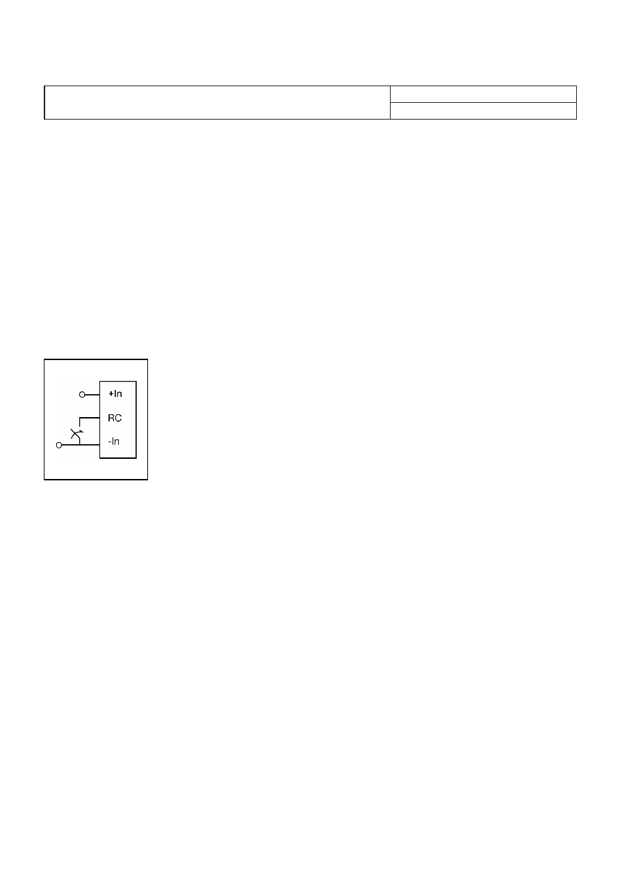
Remote Control (RC)
The products are fitted with a
remote control function referenced
to the primary negative input
connection (- In), with negative and
positive logic options available.
The RC function allows the
converter to be turned on/off by an
external device like a
semiconductor or mechanical
switch. The RC pin has an internal
pull up resistor to + In.
The maximum required sink current is 0.6 mA. When the RC
pin is left open, the voltage generated on the RC pin is
10 — 22 V. The maximum allowable leakage current of the
switch is 50 A. With “negative logic” the converter will turn
on when the input voltage is applied with the RC connected
to the - In. Turn off is achieved by leaving the RC pin open, or
connected to a voltage higher than 8 V referenced to —In.
The second option is “positive logic” remote control, which
can be ordered by adding the suffix “P” to the end of the part
number. The converter will turn on when the input voltage is
applied with the RC pin open. Turn off is achieved by
connecting the RC pin to the - In. To ensure safe turn off the
voltage difference between RC pin and the - In pin shall be
less than 1 V. The converter will restart automatically when
this connection is opened.
See Design Note 021 for detailed information.
Input and Output Impedance
The impedance of both the input source and the load will
interact with the impedance of the DC/DC converter. It is
important that the input source has low characteristic
impedance. The converters are designed for stable operation
without external capacitors connected to the output. It is
recommended to use an external capacitor of minimum 1 F
on the the input. The performance in some applications can
be enhanced by addition of external capacitance as
described under External Decoupling Capacitors. If the input
voltage source contains significant inductance, the addition of
a 100 F capacitor across the input of the converter will
ensure stable operation. The capacitor is not required when
powering the DC/DC converter from an input source with an
inductance below 10 H.
External Decoupling Capacitors
When powering loads with significant dynamic current
requirements, the voltage regulation at the point of load can
be improved by addition of decoupling capacitors at the load.
The most effective technique is to locate low ESR ceramic
and electrolytic capacitors as close to the load as possible,
using several parallel capacitors to lower the effective ESR.
The ceramic capacitors will handle high-frequency dynamic
load changes while the electrolytic capacitors are used to
handle low frequency dynamic load changes. Ceramic
capacitors will also reduce any high frequency noise at the
load.
It is equally important to use low resistance and low
inductance PCB layouts and cabling.
External decoupling capacitors will become part of the
control loop of the DC/DC converter and may affect the
stability margins. As a “rule of thumb”, 100 F/A of output
current can be added without any additional analysis. The
ESR of the capacitors is a very important parameter. Ericsson
Power Modules guarantee stable operation with a verified
ESR value of >10 m across the output connections.
For further information please contact your local Ericsson
Power Modules representative.
E
PKU 4000 Series
DC/DC converters, Input 36-75 V, Output 25 A/50 W
EN/LZT 146 308 R4B July 2008
Ericsson Power Modules AB
Technical Specication
30
相关PDF资料 |
PDF描述 |
|---|---|
| PKU4511PIP | 1-OUTPUT 50 W DC-DC REG PWR SUPPLY MODULE |
| PKU4418GPILB | 1-OUTPUT 45 W DC-DC REG PWR SUPPLY MODULE |
| PKU4318HPILA | 1-OUTPUT 37.5 W DC-DC REG PWR SUPPLY MODULE |
| PKU4319PIP | 1-OUTPUT 37.5 W DC-DC REG PWR SUPPLY MODULE |
| PKU4418GPILA | 1-OUTPUT 45 W DC-DC REG PWR SUPPLY MODULE |
相关代理商/技术参数 |
参数描述 |
|---|---|
| PKU4513PIPLA | 制造商:Ericsson 功能描述:1/16 BRICK, DC/DC CONVERTER, 50W, ISOLATED - Trays |
| PKU4513SI | 制造商:Ericsson 功能描述:CONVERTER/PKU4513 SI 36-75VIN/12VOUT,4.2 - Trays |
| PKU4515 PI | 制造商:Ericsson 功能描述: |
| PKU4515 SI/C | 制造商:Ericsson 功能描述: |
| PKU4515PI | 功能描述:DC/DC转换器 15Vdc 3.3A Isolated Input 36-75V 50W RoHS:否 制造商:Murata 产品: 输出功率: 输入电压范围:3.6 V to 5.5 V 输入电压(标称): 输出端数量:1 输出电压(通道 1):3.3 V 输出电流(通道 1):600 mA 输出电压(通道 2): 输出电流(通道 2): 安装风格:SMD/SMT 封装 / 箱体尺寸: |
发布紧急采购,3分钟左右您将得到回复。