- 您现在的位置:买卖IC网 > PDF目录96691 > PM150RSD060 AC MOTOR CONTROLLER, 300 A, UFM19 PDF资料下载
参数资料
| 型号: | PM150RSD060 |
| 元件分类: | 运动控制电子 |
| 英文描述: | AC MOTOR CONTROLLER, 300 A, UFM19 |
| 文件页数: | 4/9页 |
| 文件大小: | 150K |
| 代理商: | PM150RSD060 |
MITSUBISHI <INTELLIGENT POWER MODULES>
PM150RSD060
FLAT-BASE TYPE
INSULATED PACKAGE
Jul. 2005
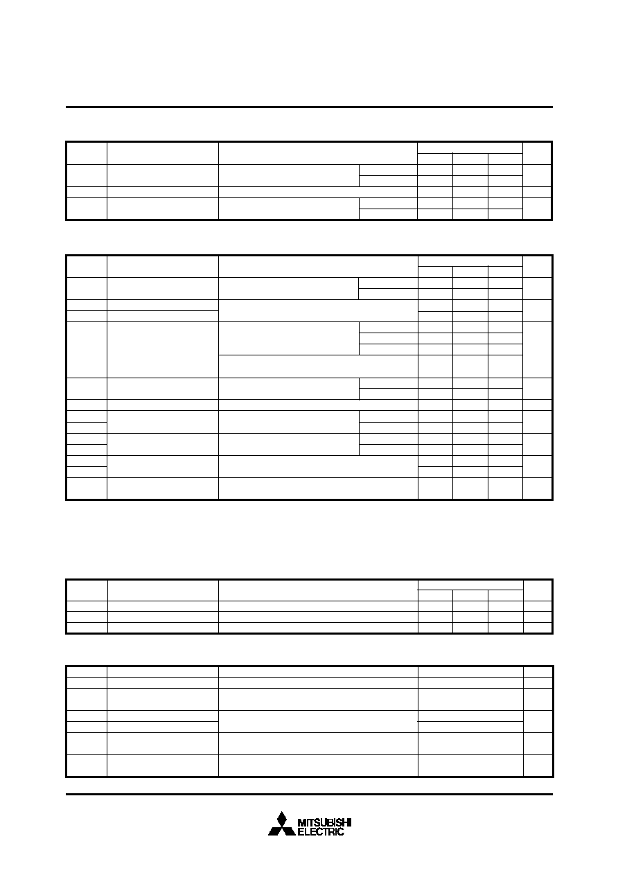
RECOMMENDED CONDITIONS FOR USE
Recommended value
Unit
Test Condition
Symbol
Parameter
V
Applied across P-N terminals
Applied between : VUP1-VUPC, VVP1-VVPC
VWP1-VWPC, VN1-VNC
(Note-4)
Applied between : UP-VUPC, VP-VVPC, WP-VWPC
UN VN WN Br-VNC
Using Application Circuit input signal of IPM, 3
φ
sinusoidal PWM VVVF inverter
(Fig. 8)
For IPM’s each input signals
(Fig. 7)
Supply Voltage
Control Supply Voltage
Input ON Voltage
Input OFF Voltage
PWM Input Frequency
Arm Shoot-through
Blocking Time
≤ 400
15
± 1.5
≤ 0.8
≥ 4.0
≤ 20
≥ 2.5
VCC
VCIN(ON)
VCIN(OFF)
fPWM
tdead
VD
V
kHz
s
V
(Note-4) Allowable Ripple rating of Control Voltage : dv/dt
≤ ±5V/ms, 2Vp-p
VD = 15V, VCIN = 15V
Applied between : UP-VUPC, VP-VVPC, WP-VWPC
UN VN WN Br-VNC
ID
°C
V
mA
ms
72
18
1.8
2.3
690
570
—
125
—
12.5
—
0.01
15
—
mA
Circuit Current
Input ON Threshold Voltage
Input OFF Threshold Voltage
Over Current Trip Level
Short Circuit Trip Level
Over Current Delay Time
Over Temperature Protection
Supply Circuit Under-Voltage
Protection
Fault Output Current
Minimum Fault Output Pulse
Width
Vth(ON)
Vth(OFF)
OC
SC
toff(OC)
OT
OTr
UV
UVr
IFO(H)
IFO(L)
tFO
Trip level
Reset level
Trip level
Reset level
CONTROL PART
—
1.2
1.7
—
351
210
65
—
111
—
11.5
—
1.0
Parameter
Symbol
Test Condition
Max.
Min.
Typ.
Unit
Limits
52
13
1.5
2.0
—
413
—
88
420
132
10
118
100
12.0
12.5
—
10
1.8
(Note-3) Fault output is given only when the internal OC, SC, OT & UV protection.
Fault output of OC, SC and UV protection operate by upper and lower arms.
Fault output of OT protection operate by lower arm.
Fault output of OC, SC protection given pulse.
Fault output of OT, UV protection given pulse while over level.
Base-plate
Temperature detection, VD = 15V
–20
≤ Tj ≤ 125°C
VD = 15V, VFO = 15V
(Note-3)
VD = 15V
(Note-3)
V
s
Inverter part
VD = 15V
(Fig. 5,6)
Break part
–20
≤ Tj ≤ 125°C, VD = 15V
(Fig. 5,6)
–20
≤ Tj ≤ 125°C, VD = 15V (Fig. 5,6)
VD = 15V
(Fig. 5,6)
VN1-VNC
VXP1-VXPC
Tj = –20
°C
Tj = 25
°C
Tj = 125
°C
Inverter part
Brake part
A
—
VCE(sat)
ICES
VFM
V
mA
Min.
Typ.
Max.
V
Collector-Emitter
Saturation Voltage
FWDi Forward Voltage
Collector-Emitter
Cutoff Current
IF = 50A
(Fig. 2)
Tj = 25
°C
Tj = 125
°C
Unit
Parameter
Symbol
Test Condition
Limits
2.80
3.05
3.3
1
10
2.35
2.55
2.2
—
Tj = 25
°C
Tj = 125
°C
BRAKE PART
VD = 15V, IC = 50A
VCIN = 0V, Pulsed
(Fig. 1)
VCE = VCES, VCIN = 15V
(Fig. 4)
3.5
—
Main terminal
screw : M5
Mounting part
screw : M5
—
Symbol
Parameter
Mounting torque
Weight
Test Condition
Unit
N m
g
Limits
Min.
Typ.
Max.
2.5
—
3.0
560
MECHANICAL RATINGS AND CHARACTERISTICS
相关PDF资料 |
PDF描述 |
|---|---|
| PM15CHA060 | AC MOTOR CONTROLLER, DMA20 |
| PM15CTM060-3 | AC MOTOR CONTROLLER, 30 A, XMA20 |
| PM15CTM060 | AC MOTOR CONTROLLER, 30 A, XMA20 |
| PM15CZF120 | AC MOTOR CONTROLLER, 30 A, DMA20 |
| PM15RHB120 | AC MOTOR CONTROLLER, XMA22 |
相关代理商/技术参数 |
参数描述 |
|---|---|
| PM150RSD060_05 | 制造商:MITSUBISHI 制造商全称:Mitsubishi Electric Semiconductor 功能描述:INTELLIGENT POWER MODULES FLAT-BASE TYPE INSULATED PACKAGE |
| PM150RSD120 | 功能描述:MOD IPM 7PAC 1200V 150A RoHS:是 类别:半导体模块 >> 功率驱动器 系列:Intellimod™ 标准包装:15 系列:SPM® 类型:FET 配置:三相反相器 电流:1.8A 电压:500V 电压 - 隔离:1500Vrms 封装/外壳:23-DIP 模块 |
| PM150RSD120_05 | 制造商:MITSUBISHI 制造商全称:Mitsubishi Electric Semiconductor 功能描述:INTELLIGENT POWER MODULES FLAT-BASE TYPE INSULATED PACKAGE |
| PM150RSE060 | 制造商:MITSUBISHI 制造商全称:Mitsubishi Electric Semiconductor 功能描述:FLAT-BASE TYPE INSULATED PACKAGE |
| PM150RSE060_05 | 制造商:MITSUBISHI 制造商全称:Mitsubishi Electric Semiconductor 功能描述:INTELLIGENT POWER MODULES FLAT-BASE TYPE INSULATED PACKAGE |
发布紧急采购,3分钟左右您将得到回复。