- 您现在的位置:买卖IC网 > PDF目录69063 > PME5218TS (ERICSSON POWER MODULES AB) 1-OUTPUT 21.6 W DC-DC REG PWR SUPPLY MODULE PDF资料下载
参数资料
| 型号: | PME5218TS |
| 厂商: | ERICSSON POWER MODULES AB |
| 元件分类: | 电源模块 |
| 英文描述: | 1-OUTPUT 21.6 W DC-DC REG PWR SUPPLY MODULE |
| 封装: | ROHS COMPLIANT, SMD-6 |
| 文件页数: | 17/32页 |
| 文件大小: | 742K |
| 代理商: | PME5218TS |
第1页第2页第3页第4页第5页第6页第7页第8页第9页第10页第11页第12页第13页第14页第15页第16页当前第17页第18页第19页第20页第21页第22页第23页第24页第25页第26页第27页第28页第29页第30页第31页第32页
Ericsson Internal
PRODUCT SPEC.
2 (5)
Prepared (also subject responsible if other)
No.
SEC/D KEVIN YAN
3/1301-BMR 642 5 Uen
Approved
Checked
Date
Rev
Reference
SEC/D Wei Zhang A
2007-1-26
B
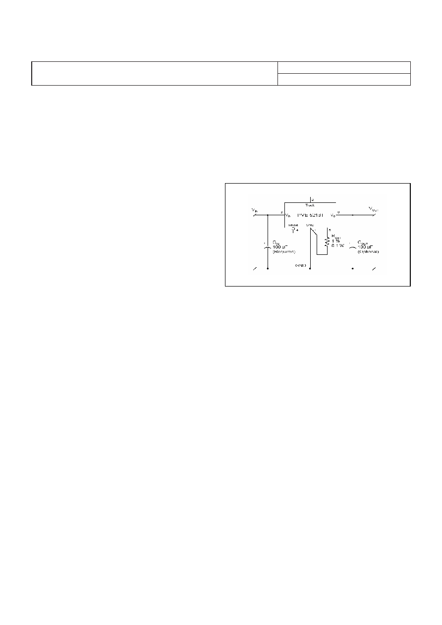
External Capacitors
Input capacitors:
The recommended input capacitors are determined by the
100 μF minimum capacitance and 300 mArms minimum
ripple current rating.
Output capacitors (optional):
The recommended output capacitance of 100 μF will allow
the module to meet its transient response specification as
defined in the electrical specification.
When using one or more non-ceramic capacitors, the
calculated equivalent ESR should be no lower than 4 mΩ
(7mΩ using the manufacturer’s maximum ESR for a single
capacitor).
Input And Output Impedance
The impedance of both the input source and the load will
interact with the impedance of the DC/DC regulator. It is
important that the input source has low characteristic
impedance. The regulators are designed for stable operation
without external capacitors connected to the input or output.
The performance in some applications can be enhanced by
addition of external capacitance as described under External
Decoupling Capacitors. If the input voltage source contains
significant inductance, the addition of a 100 μF capacitor
across the input of the regulator will ensure stable operation.
The capacitor is not required when powering the DC/DC
regulator from an input source with an inductance below
10 μH.
External Decoupling Capacitors
When powering loads with significant dynamic current
requirements, the voltage regulation at the point of load can
be improved by addition of decoupling capacitors at the load.
The most effective technique is to locate low ESR ceramic
and electrolytic capacitors as close to the load as possible,
using several parallel capacitors to lower the effective ESR.
The ceramic capacitors will handle high-frequency dynamic
load changes while the electrolytic capacitors are used to
handle low frequency dynamic load changes. Ceramic
capacitors will also reduce any high frequency noise at the
load.
It is equally important to use low resistance and low
inductance PCB layouts and cabling.
External decoupling capacitors will become part of the
control loop of the DC/DC regulator and may affect the
stability margins. As a “rule of thumb”, 100 μF/A of output
current can be added without any additional analysis. The
ESR of the capacitors is a very important parameter. Power
Modules guarantee stable operation with a verified ESR value
of >10 m across the output connections.
For further information please contact your local Ericsson
Power Modules representative.
Output Voltage Adjust (Vadj)
The DC/DC regulators have an Output Voltage Adjust pin
(Vadj). This pin can be used to adjust the output voltage above
or below Output voltage initial setting.
To increase or decrease the voltage the resistor should be
connected between the Vadj pin and GND pin. The resistor
value of the Output voltage adjust function is according to
information given under the Output section for the respective
product.
Parallel Operation
Two regulators may be paralleled for redundancy if the total
power is equal or less than PO max. It is not recommended to
parallel the regulators without using external current sharing
circuits.
Over Current Protection (OCP)
The regulators include current limiting circuitry for protection
at continuous overload.
The output voltage will decrease towards zero for output
currents in excess of the over-current threshold. The regulator
will resume normal operation after removal of the overload.
The load distribution should be designed for the maximum
output short circuit current specified. The current limit
operation is a “hick up” mode current limit.
Soft-start Power Up
From the moment a valid input voltage is applied, the soft-
start control introduces a short time-delay (typically 5-10 ms)
before allowing the output voltage to rise.
The initial rise in input current when the input voltage first
starts to rise is the charge current drawn by the input
capacitors. Power-up is complete within 15 ms.
E
PME 5000 series
POL regulator, Input 4.5-5.5 V, Output 6 A/21.6 W
EN/LZT 146 314 R1B Aug 2007
Ericsson Power Modules AB
Technical Specication
24
相关PDF资料 |
PDF描述 |
|---|---|
| PMF4118VSRF | POWER SUPPLY SUPPORT CKT, DMA10 |
| PMF4118VPF | POWER SUPPLY SUPPORT CKT, DMA10 |
| PMF8118VSRF | 1-OUTPUT 12.5 W DC-DC REG PWR SUPPLY MODULE |
| PMF8118VSF | 1-OUTPUT 12.5 W DC-DC REG PWR SUPPLY MODULE |
| PMF8118VPF | 1-OUTPUT 12.5 W DC-DC REG PWR SUPPLY MODULE |
相关代理商/技术参数 |
参数描述 |
|---|---|
| PME5218TSR | 功能描述:DC/DC转换器 0.8-3.6V 6A Non-Iso Input 5V 21.6W RoHS:否 制造商:Murata 产品: 输出功率: 输入电压范围:3.6 V to 5.5 V 输入电压(标称): 输出端数量:1 输出电压(通道 1):3.3 V 输出电流(通道 1):600 mA 输出电压(通道 2): 输出电流(通道 2): 安装风格:SMD/SMT 封装 / 箱体尺寸: |
| PME-5FF-RYGBC | 制造商:Autonics Corporation 功能描述:TOWER LIGHT 90-240VAC 163mA 制造商:Autonics Corporation 功能描述:TOWER LIGHT, 90-240VAC, 163mA 制造商:Autonics Corporation 功能描述:TOWER LIGHT, 90-240VAC, 163mA, IP / NEMA Rating:IP56, Flash Rate Per Minute:80, |
| PME60-619KOHMSPORM1PCT | 制造商: 功能描述: 制造商:undefined 功能描述: |
| PME8118TP | 功能描述:DC/DC转换器 0.8-1.8V 6A Non-Iso Input 12V 10.8W RoHS:否 制造商:Murata 产品: 输出功率: 输入电压范围:3.6 V to 5.5 V 输入电压(标称): 输出端数量:1 输出电压(通道 1):3.3 V 输出电流(通道 1):600 mA 输出电压(通道 2): 输出电流(通道 2): 安装风格:SMD/SMT 封装 / 箱体尺寸: |
| PME8118TS | 功能描述:DC/DC转换器 .8-1.8 Vdc 6A Iso Input 5V 10.8W RoHS:否 制造商:Murata 产品: 输出功率: 输入电压范围:3.6 V to 5.5 V 输入电压(标称): 输出端数量:1 输出电压(通道 1):3.3 V 输出电流(通道 1):600 mA 输出电压(通道 2): 输出电流(通道 2): 安装风格:SMD/SMT 封装 / 箱体尺寸: |
发布紧急采购,3分钟左右您将得到回复。