- 您现在的位置:买卖IC网 > PDF目录98060 > PS11NG (SUPERTEX INC) 1-CHANNEL POWER SUPPLY SUPPORT CKT, PDSO14 PDF资料下载
参数资料
| 型号: | PS11NG |
| 厂商: | SUPERTEX INC |
| 元件分类: | 电源管理 |
| 英文描述: | 1-CHANNEL POWER SUPPLY SUPPORT CKT, PDSO14 |
| 封装: | SOIC-14 |
| 文件页数: | 7/14页 |
| 文件大小: | 210K |
| 代理商: | PS11NG |
PS10/PS11
2
A051204
*Absolute Maximum Ratings are those values beyond which damage to the device may
occur. Functional operation under these conditions is not implied. Continuous operation of
the device at the absolute rating level may affect device reliability. All voltages are refer-
enced to device ground.
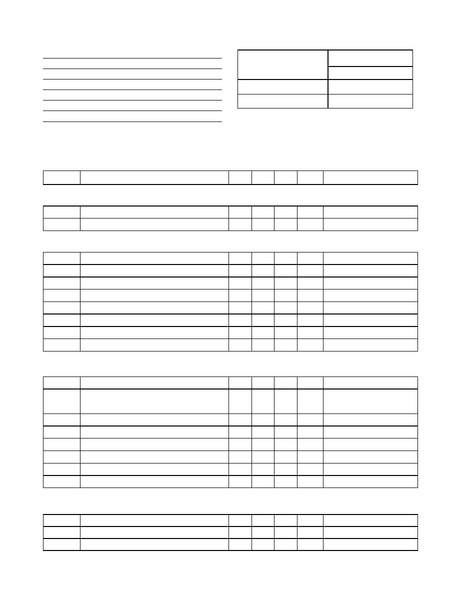
Ordering Information
Package Options
Active State of Power
Good Flags
14 Pin SOIC
High
PS10NG
Low
PS11NG
Absolute Maximum Ratings*
V
EE referenced to VIN pin
+0.3V to -100V
V
PWRGD referenced to VEE voltage
-0.3V to +100V
V
UV and VOV referenced to VEE Voltage
-0.3V to 12V
Operating Ambient Temperature
-40°C to +85°C
Operating Junction Temperature
-40°C to +125°C
Storage Temperature Range
-65° to +150°C
Power Dissipation @ 25
°C, 14-Pin SOIC
750mW
Electrical Characteristics (-10V V
IN -90V, TA = 25°C unless otherwise specified)
Symbol
Parameter
Min
Typ
Max
Units
Conditions
Supply (Referenced to V
IN pin)
V
EE
Supply Voltage
-90
-10
V
I
EE
Supply Current
400
450
A
V
EE = -48V
OV and UV Control (Referenced to V
EE pin)
V
UVH
UV High Threshold
#
1.16
1.22
1.28
V
Low to High Transition
V
UVL
UV Low Threshold
#
1.06
1.12
1.18
V
High to Low Transition
V
UVHY
UV Hysteresis
#
100
mV
I
UV
UV Input Current
1.0
nA
V
UV = VEE + 1.9V
V
OVH
OV High Threshold
#
1.16
1.22
1.28
V
Low to High Transition
V
OVL
OV Low Threshold
#
1.06
1.12
1.18
V
High to Low Transition
V
OVHY
OV Hysteresis
#
100
mV
I
OV
OV Input Current
1.0
nA
V
UV = VEE + 1.9V
#Specifications apply over 0
°C ≤ T
A ≤ 70°C
Power Good Timing (Test Conditions: C
RAMP = 10nF, VUV = VEE + 1.9V, VOV = VEE + 0.5V)
I
RAMP
Ramp Pin Output Current
10
A
t
PWRGD-A
Time from UV High to PWRGD-A
8.8
ms
V
EE = -48V, CRAMP = 10nF,
see Typical Application Cir-
cuit
t
PWRGD-B
Maximum time from PWRGD-A to PWRGD-B
150
200*
250
ms
RTB = 120k
t
PWRGD-B
Minimum time from PWRGD-A to PWRGD-B
3.0
5.0*
8.0
ms
RTB = 3k
t
PWRGD-C
Maximum time from PWRGD-B to PWRGD-C
150
200*
250
ms
RTC = 120k
t
PWRGD-C
Minimum time from PWRGD-B to PWRGD-C
3.0
5.0*
8.0
ms
RTC = 3k
t
PWRGD-D
Maximum time from PWRGD-C to PWRGD-D
150
200*
250
ms
RTD = 120k
t
PWRGD-D
Minimum time from PWRGD-C to PWRGD-D
3.0
5.0*
8.0
ms
RTD = 3k
*Note: Variations will track. For example if t
PWRGD-A is 250ms then so will be tPWRGD-B/C/D. Contact factory for tighter tolerance version.
Power Good Outputs (Test Conditions: V
UV = VEE + 1.9V, VOV = VEE + 0.5V)
V
PWRGD-x(hi)
Power Good Pin Breakdown Voltage
90
V
PWRGD-x = HI Z
V
PWRGD-x(lo)
Power Good Pin Output Low Voltage
0.4
0.5
V
I
PWRGD = 1mA, PWRGD-x = LOW
I
PWRGD-x(lk)
Maximum Leakage Current
<1.0
10
A
V
PWRGD = 90V, PWRGD-x = HI Z
相关PDF资料 |
PDF描述 |
|---|---|
| PS395ACPG | OCTAL 1-CHANNEL, SGL POLE SGL THROW SWITCH, PDIP24 |
| PS395AEWG | OCTAL 1-CHANNEL, SGL POLE SGL THROW SWITCH, PDSO24 |
| PS395CNB | OCTAL 1-CHANNEL, SGL POLE SGL THROW SWITCH, PDIP24 |
| PS395ENG | OCTAL 1-CHANNEL, SGL POLE SGL THROW SWITCH, PDIP24 |
| PS395CWG | OCTAL 1-CHANNEL, SGL POLE SGL THROW SWITCH, PDSO24 |
相关代理商/技术参数 |
参数描述 |
|---|---|
| PS11NG-G | 功能描述:DC/DC 开关控制器 Quad Pwr Seq Cntlr RoHS:否 制造商:Texas Instruments 输入电压:6 V to 100 V 开关频率: 输出电压:1.215 V to 80 V 输出电流:3.5 A 输出端数量:1 最大工作温度:+ 125 C 安装风格: 封装 / 箱体:CPAK |
| PS11NG-M905 | 功能描述:DC/DC 开关控制器 Quad Pwr Seq Ctlr RoHS:否 制造商:Texas Instruments 输入电压:6 V to 100 V 开关频率: 输出电压:1.215 V to 80 V 输出电流:3.5 A 输出端数量:1 最大工作温度:+ 125 C 安装风格: 封装 / 箱体:CPAK |
| PS11NG-M905-G | 功能描述:DC/DC 开关控制器 Quad Pwr Seq Ctlr RoHS:否 制造商:Texas Instruments 输入电压:6 V to 100 V 开关频率: 输出电压:1.215 V to 80 V 输出电流:3.5 A 输出端数量:1 最大工作温度:+ 125 C 安装风格: 封装 / 箱体:CPAK |
| PS12 | 制造商:Panduit Corp 功能描述: |
| PS-12 | 功能描述:罩类、盒类及壳类产品 RoHS:否 制造商:Bud Industries 产品:Boxes 外部深度:6.35 mm 外部宽度:6.35 mm 外部高度:2.56 mm NEMA 额定值: IP 等级: 材料:Acrylonitrile Butadiene Styrene (ABS) 颜色:Red |
发布紧急采购,3分钟左右您将得到回复。