- 您现在的位置:买卖IC网 > PDF目录97636 > PS21A7A (POWEREX INC) AC MOTOR CONTROLLER, 150 A, XMA42 PDF资料下载
参数资料
| 型号: | PS21A7A |
| 厂商: | POWEREX INC |
| 元件分类: | 运动控制电子 |
| 英文描述: | AC MOTOR CONTROLLER, 150 A, XMA42 |
| 文件页数: | 2/7页 |
| 文件大小: | 771K |
| 代理商: | PS21A7A |
PS21A7A
Intellimod Module
Dual-In-Line Intelligent Power Module
75 Amperes/600 Volts
Powerex, Inc., 173 Pavilion Lane,Youngwood, Pennsylvania 15697 (724) 925-7272
2
Rev. 08/09
Absolute Maximum Ratings, Tj = 25°C unless otherwise specified
Characteristics
Symbol
PS21A7A
Units
Self-protection Supply Voltage Limit (Short Circuit Protection Capability)*
VCC(prot.)
400
Volts
Module Case Operation Temperature (See TC Measurement Point Below)
TC
-20 to 100
°C
Storage Temperature
Tstg
-40 to 125
°C
Mounting Torque, M4 Mounting Screws
—
13
in-lb
Module Weight (Typical)
—
65
Grams
Isolation Voltage, AC 1 minute, 60Hz Sinusoidal, Connection Pins to Heatsink Plate
VISO
2500
Volts
IGBT Inverter Sector
Supply Voltage (Applied between P-NU, NV, NW)
VCC
450
Volts
Supply Voltage, Surge (Applied between P-NU, NV, NW)
VCC(surge)
500
Volts
Collector-Emitter Voltage (TC = 25°C)
VCES
600
Volts
Collector Current (TC = 25°C)
±IC
75
Amperes
Peak Collector Current (TC = 25°C, <1ms)
±ICP
150
Amperes
Collector Dissipation (TC = 25°C, per 1 Chip)
PC
162
Watts
Power Device Junction Temperature**
Tj
-20 to 150
°C
Control Sector
Supply Voltage (Applied between VP1-VPC, VN1-VNC)
VD
20
Volts
Supply Voltage (Applied between VUFB-VUFS, VVFB-VVFS, VWFB-VWFS)
VDB
20
Volts
Input Voltage (Applied between UP, VP, WP-VPC, UN, VN, WN-VNC)
VIN
-0.5 ~ VD+0.5
Volts
Fault Output Supply Voltage (Applied between FO-VNC)
VFO
-0.5 ~ VD+0.5
Volts
Fault Output Current (Sink Current at FO Terminal)
IFO
1
mA
Current Sensing Input Voltage (Applied between CIN-VNC)
VSC
-0.5 ~ VD+0.5
Volts
*VD = 13.5 ~ 16.5V, Inverter Part, Tj = 125°C, Non-repetitive, Less than 2s
**The maximum junction temperature rating of the power chips integrated within the DIPIPM is 150°C (@Tf ≤ 100°C). However, to ensure safe operation of the DIPIPM,
the average junction temperature should be limited to Tj(avg) ≤ 125°C (@Tf ≤ 100°C).
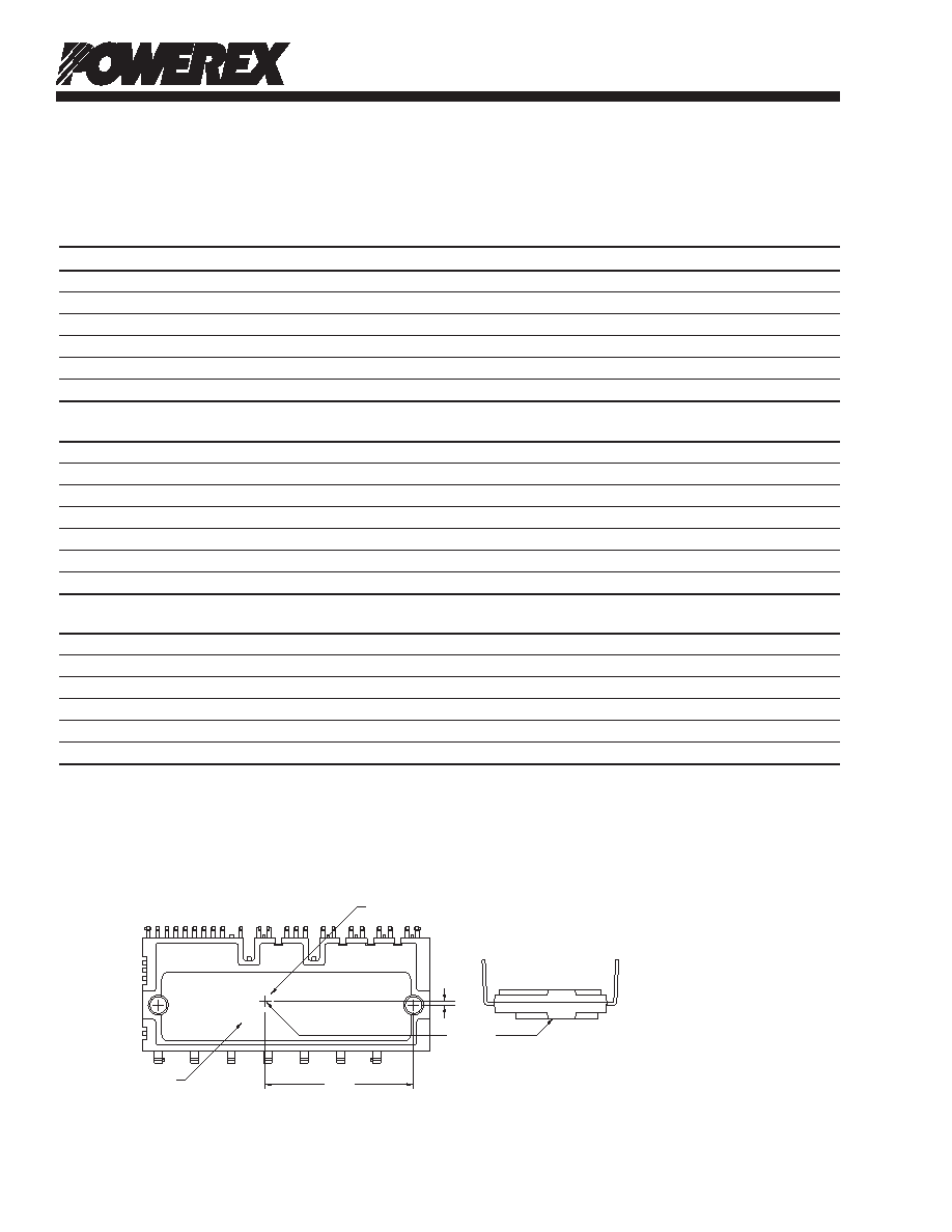
TC Measurement Point
IGBT CHIP
BUILT-IN HEATSINK
1.2
40.5
TC POINT
相关PDF资料 |
PDF描述 |
|---|---|
| PS22053 | AC MOTOR CONTROLLER, 20 A, DMA28 |
| PS22A72 | AC MOTOR CONTROLLER, 10 A, DMA42 |
| PSDM-0DT2-5020 | 2-OUTPUT DC-DC REG PWR SUPPLY MODULE |
| PSDM-0DO2-5040 | 2-OUTPUT DC-DC REG PWR SUPPLY MODULE |
| PST611XM | 1-CHANNEL POWER SUPPLY SUPPORT CKT, PDSO4 |
相关代理商/技术参数 |
参数描述 |
|---|---|
| PS21H-NS02HC-T00 | 制造商:Carlo Gavazzi 功能描述:2NC SNAP ZINC PLATED STEEL LVR |
| PS21H-NS02HC-Y00 | 制造商:Carlo Gavazzi 功能描述: |
| PS21H-NS02HS-T00 | 制造商:Carlo Gavazzi 功能描述: |
| PS21H-NS02HS-Y00 | 制造商:Carlo Gavazzi 功能描述:LSW 2NC SNAP STNLS STL SHAFT |
| PS21H-NS02HZ-T00 | 制造商:Carlo Gavazzi 功能描述: |
发布紧急采购,3分钟左右您将得到回复。