参数资料
| 型号: | PS5162EV |
| 厂商: | Microchip Technology |
| 文件页数: | 2/10页 |
| 文件大小: | 0K |
| 描述: | KIT EVALUATION PS5162 W/PS051 |
| 标准包装: | 1 |
�� �
�
�PS5162�
�1.0�
�GENERAL� DESCRIPTION�
�Step� 1)� Configure� the� module� for� optional� external�
�thermistor� use.� PS5162� modules� are�
�The� PS5162� module� is� a� complete� smart� battery�
�controller� subsystem� based� on� the� Microchip� PS501�
�field� reprogrammable� battery� manager� with� patented�
�Accuron� ?� technology.� The� module� is� designed� to� oper-�
�ate� in� a� battery� pack� consisting� of� two� (2)� series� con-�
�nected� Li-based� cells.� The� module� consists� of� the�
�Microchip� PS501� battery� manager� IC� with� a� four-LED�
�SOC� display� and� an� optional� connection� for� an� external�
�thermistor.�
�shipped� configured� to� use� the� internal� tem-�
�perature� sensor� only.� To� add� an� external�
�thermistor� to� the� board,� remove� resistor�
�R16� (side� 2)� and� connect� the� thermistor�
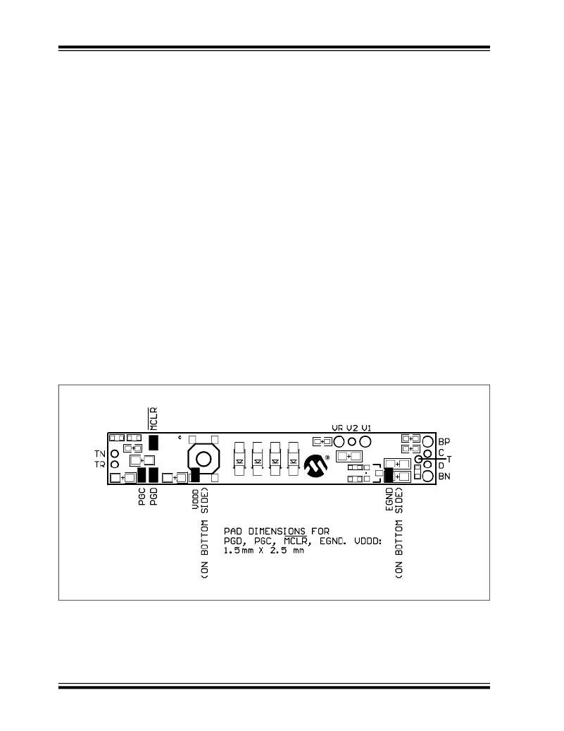
�across� via� TN� and� TR.�
�Step� 2)� Connect� wires� to� module.� Use� large� diame-�
�ter� wire� (18� AWG-20� AWG)� for� current�
�carrying� lines� from� VR,� V1,� BP� and� BN.� All�
�others� are� signal� only� lines� (24� to� 22� AWG).�
�1.1�
�Quick� Start� –� Pack� Assembly�
�Step� 3)� Connect� external� connector� to� BN,� T,� C,� D�
�and� BP.�
�Follow� these� directions� to� assemble� a� pack� with� the�
�PS5162� module.�
�?� Use� standard� precautions� when� handling� static�
�sensitive� devices.�
�?� Modules� should� be� connected� to� battery� cells� in�
�the� order� indicated� below� to� insure� proper� start-up�
�and� operation.� Wires� should� be� attached� to� the�
�modules� first� and� then� connected� to� the� battery�
�cells� as� instructed.�
�?� The� connection� sequence� is� critical� to� successful�
�use� of� the� PS501� family� of� CMOS� ASICs.� The�
�pack� positive� should� be� securely� connected� to� the�
�module� first,� followed� by� the� intermediate� cell�
�connection� and� then� pack� negative.�
�Step� 4)� Connect� V1� to� the� most� positive� point� on�
�the� battery� cell� stack.�
�Step� 5)� Connect� V2� to� the� middle� of� the� cell� stack.�
�Step� 6)� Connect� VR� to� the� most� negative� point� on�
�the� battery� cell� stack.�
�Step� 7)� Program� the� assembled� pack� using�
�Microchip’s� software� and� PowerCal?�
�board� or� PowerInfo?� board� hardware.�
�The� memory� parameters� can� be� changed� at�
�will� using� the� utilities� on� the� memory� page� in�
�the� software.�
�Step� 8)� Calibrate� the� pack� using� the� software� and�
�PowerCal?� board� hardware.� The� pack� is�
�now� ready� for� use.�
�FIGURE� 1-1:�
�DS21842B-page� 2�
�CONNECTION� POINTS� (SIDE� 1)�
�?� 2004� Microchip� Technology� Inc.�
�相关PDF资料 |
PDF描述 |
|---|---|
| PS5163 | MODULE BATTERY MGR W/LED DISPLAY |
| PS5164EV | KIT EVALUATION PS5164 W/PS051 |
| PS7070EV | BOARD EVAL PS700 W/POWERINFO2 |
| PTGL09AS1R2K2B51B0 | THERMISTOR PTC 30V 1.2 OHM 10% |
| PX0447 | CONN IP68 B MINI USB W/PINS PCB |
相关代理商/技术参数 |
参数描述 |
|---|---|
| PS5163 | 功能描述:电源管理模块 2 CELL LI ION/POLY RoHS:否 制造商:ROHM Semiconductor 产品:AC-DC Converters 最大输入电压:264 VAC 开关频率: 输出电压:10 V to 28.8 V 输出电流:350mA 负载调节: 最大工作温度:+ 60 C 尺寸:100 mm x 16 mm x 17 mm |
| PS5163EV | 功能描述:电源管理IC开发工具 2 CELL LI ION/POLY RoHS:否 制造商:Maxim Integrated 产品:Evaluation Kits 类型:Battery Management 工具用于评估:MAX17710GB 输入电压: 输出电压:1.8 V |
| PS5164 | 功能描述:电源管理模块 2 CELL LI ION/POLY RoHS:否 制造商:ROHM Semiconductor 产品:AC-DC Converters 最大输入电压:264 VAC 开关频率: 输出电压:10 V to 28.8 V 输出电流:350mA 负载调节: 最大工作温度:+ 60 C 尺寸:100 mm x 16 mm x 17 mm |
| PS5164EV | 功能描述:电源管理IC开发工具 2 CELL LI ION/POLY RoHS:否 制造商:Maxim Integrated 产品:Evaluation Kits 类型:Battery Management 工具用于评估:MAX17710GB 输入电压: 输出电压:1.8 V |
| PS5171 | 制造商:Aleph America Corporation 功能描述: |
发布紧急采购,3分钟左右您将得到回复。