- 您现在的位置:买卖IC网 > PDF目录368226 > PSD4235G1-12MI (意法半导体) Flash In-System Programmable ISP Peripherals For 16-bit MCUs 5V Supply PDF资料下载
参数资料
| 型号: | PSD4235G1-12MI |
| 厂商: | 意法半导体 |
| 英文描述: | Flash In-System Programmable ISP Peripherals For 16-bit MCUs 5V Supply |
| 中文描述: | Flash在系统可编程ISP的外设的16位微控制器5V电源 |
| 文件页数: | 8/89页 |
| 文件大小: | 703K |
| 代理商: | PSD4235G1-12MI |
第1页第2页第3页第4页第5页第6页第7页当前第8页第9页第10页第11页第12页第13页第14页第15页第16页第17页第18页第19页第20页第21页第22页第23页第24页第25页第26页第27页第28页第29页第30页第31页第32页第33页第34页第35页第36页第37页第38页第39页第40页第41页第42页第43页第44页第45页第46页第47页第48页第49页第50页第51页第52页第53页第54页第55页第56页第57页第58页第59页第60页第61页第62页第63页第64页第65页第66页第67页第68页第69页第70页第71页第72页第73页第74页第75页第76页第77页第78页第79页第80页第81页第82页第83页第84页第85页第86页第87页第88页第89页
PSD4235G2
8/89
PSD ARCHITECTURAL OVERVIEW
PSD devices contain several major functional
blocks. Figure 4 shows the architecture of the PSD
device family. The functions of each block are de-
scribed briefly in the following sections. Many of
the blocks perform multiple functions and are user
configurable.
Memory
Each of the memory blocks is briefly discussed in
the following paragraphs. A more detailed discus-
sion can be found in the section entitled “Memory
Blocks“ on page 20.
The 4 Mbit primary Flash memory is the main
memory of the PSD. It is divided into 8 equally-
sized sectors that are individually selectable.
The 256 Kbit secondary Flash memory is divided
into 4 equally-sized sectors. Each sector is individ-
ually selectable.
The 64 Kbit SRAM is intended for use as a
scratch-pad memory or as an extension to the
MCU SRAM. If an external battery is connected to
the PSD’s Voltage Stand-by (VSTBY, PE6) signal,
data is retained in the event of power failure.
Each memory block can be located in a different
address space as defined by the user. The access
times for all memory types includes the address
latching and DPLD decoding time.
PLDs
The device contains two PLD blocks, the Decode
PLD (DPLD) and the Complex PLD (CPLD), as
shown in Table 2, each optimized for a different
function. The functional partitioning of the PLDs
reduces power consumption, optimizes cost/per-
formance, and eases design entry.
The DPLD is used to decode addresses and to
generate Sector Select signals for the PSD inter-
nal memory and registers. The DPLD has combi-
natorial outputs, while the CPLD can implement
more general user-defined logic functions. The
CPLD has 16 Output Macrocells (OMC) and 8
combinatorial outputs. The PSD also has 24 Input
Macrocells (IMC) that can be configured as inputs
to the PLDs. The PLDs receive their inputs from
the PLD Input Bus and are differentiated by their
output destinations, number of product terms, and
Macrocells.
The PLDs consume minimal power. The speed
and power consumption of the PLD is controlled
by the Turbo bit in PMMR0 and other bits in
PMMR2. These registers are set by the MCU at
run-time. There is a slight penalty to PLD propaga-
tion time when not in the Turbo mode.
I/O Ports
The PSD has 52 I/O pins divided among seven
ports (Port A, B, C, D, E, F and G). Each I/O pin
can be individually configured for different func-
tions. Ports can be configured as standard MCU I/
O ports, PLD I/O, or latched address outputs for
MCUs using multiplexed address/data buses
The JTAG pins can be enabled on Port E for In-
System Programming (ISP).
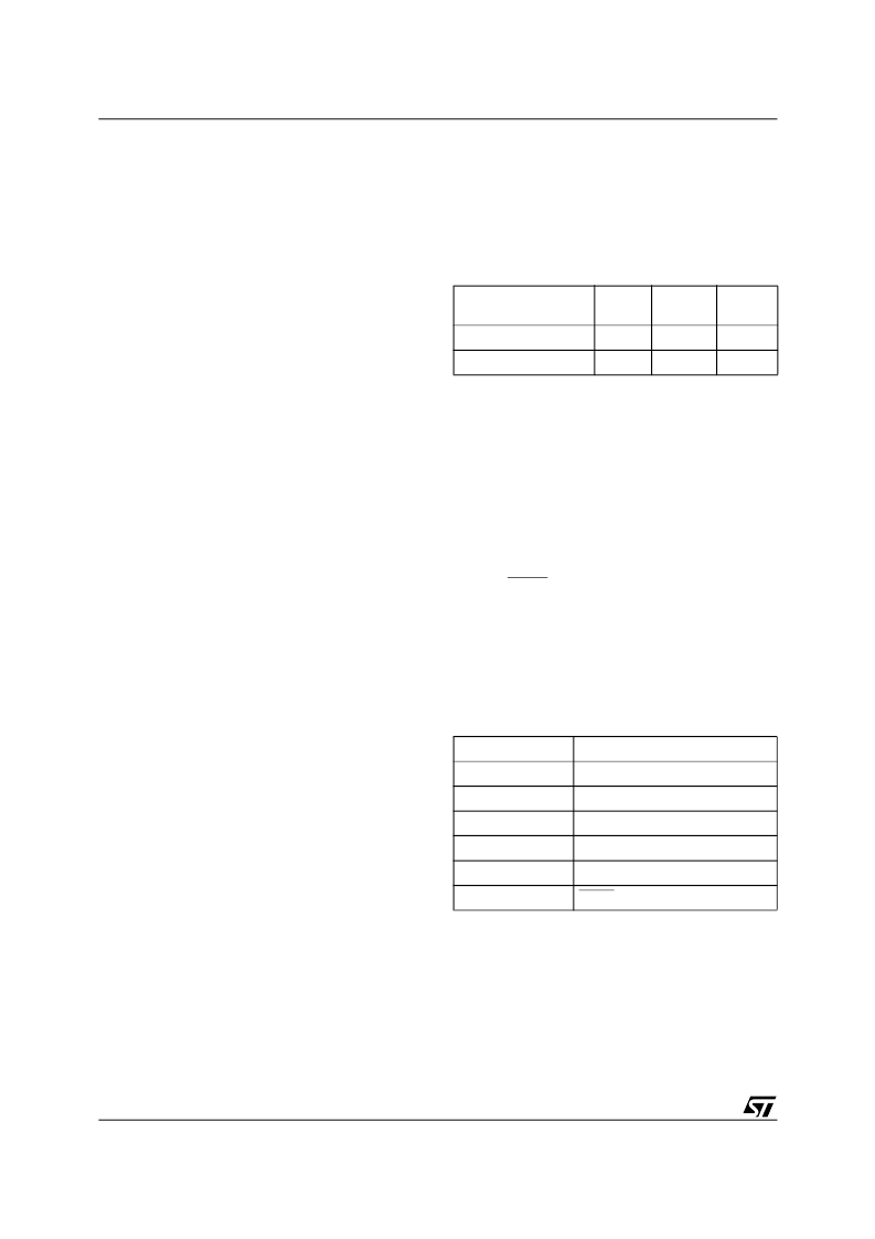
Table 2. PLD I/O
MCU Bus Interface
The PSD easily interfaces easily with most 16-bit
MCUs, either with multiplexed or non-multiplexed
address/data buses. The device is configured to
respond to the MCU’s control pins, which are also
used as inputs to the PLDs.
ISP via JTAG Port
In-System Programming (ISP) can be performed
through the JTAG signals on Port E. This serial in-
terface allows complete programming of the entire
PSD device. A blank device can be completely
programmed. The JTAG signals (TMS, TCK,
TSTAT, TERR, TDI, TDO) can be multiplexed with
other functions on Port E. Table 3 indicates the
JTAG pin assignments.
In-System Programming (ISP)
Using the JTAG signals on Port E, the entire PSD
device (memory, logic, configuration) can be pro-
grammed or erased without the use of the MCU.
Table 3. JTAG SIgnals on Port E
In-Application Programming (IAP)
The primary Flash memory can also be pro-
grammed, or re-programmed, in-system by the
MCU executing the programming algorithms out of
the secondary Flash memory, or SRAM. The sec-
ondary Flash memory can be programmed the
same way by executing out of the primary Flash
memory. Table 4 indicates which programming
methods can program different functional blocks
of the PSD.
Name
Inputs
Outputs
Product
Terms
Decode PLD (DPLD)
82
17
43
Complex PLD (CPLD)
82
24
150
Port E Pins
JTAG Signal
PE0
TMS
PE1
TCK
PE2
TDI
PE3
TDO
PE4
TSTAT
PE5
TERR
相关PDF资料 |
PDF描述 |
|---|---|
| PSD4235G1-12U | Flash In-System-Programmable Peripherals for 16-Bit MCUs |
| PSD4235G1-12UI | Flash In-System-Programmable Peripherals for 16-Bit MCUs |
| PSD4235G1V-12B81 | Flash In-System-Programmable Peripherals for 16-Bit MCUs |
| PSD4235G1V-12B81I | Flash In-System-Programmable Peripherals for 16-Bit MCUs |
| PSD4235G1V-12J | Flash In-System-Programmable Peripherals for 16-Bit MCUs |
相关代理商/技术参数 |
参数描述 |
|---|---|
| PSD4235G2-70U | 功能描述:SPLD - 简单可编程逻辑器件 5.0V 4M 70ns RoHS:否 制造商:Texas Instruments 逻辑系列:TICPAL22V10Z 大电池数量:10 最大工作频率:66 MHz 延迟时间:25 ns 工作电源电压:4.75 V to 5.25 V 电源电流:100 uA 最大工作温度:+ 75 C 最小工作温度:0 C 安装风格:Through Hole 封装 / 箱体:DIP-24 |
| PSD4235G2-90U | 功能描述:CPLD - 复杂可编程逻辑器件 5.0V 4M 90ns RoHS:否 制造商:Lattice 系列: 存储类型:EEPROM 大电池数量:128 最大工作频率:333 MHz 延迟时间:2.7 ns 可编程输入/输出端数量:64 工作电源电压:3.3 V 最大工作温度:+ 90 C 最小工作温度:0 C 封装 / 箱体:TQFP-100 |
| PSD4235G2-90UI | 功能描述:CPLD - 复杂可编程逻辑器件 5.0V 4M 90ns RoHS:否 制造商:Lattice 系列: 存储类型:EEPROM 大电池数量:128 最大工作频率:333 MHz 延迟时间:2.7 ns 可编程输入/输出端数量:64 工作电源电压:3.3 V 最大工作温度:+ 90 C 最小工作温度:0 C 封装 / 箱体:TQFP-100 |
| PSD4235G2V-12UI | 功能描述:CPLD - 复杂可编程逻辑器件 3.3V 4M 120ns RoHS:否 制造商:Lattice 系列: 存储类型:EEPROM 大电池数量:128 最大工作频率:333 MHz 延迟时间:2.7 ns 可编程输入/输出端数量:64 工作电源电压:3.3 V 最大工作温度:+ 90 C 最小工作温度:0 C 封装 / 箱体:TQFP-100 |
| PSD4235G2V-90U | 功能描述:CPLD - 复杂可编程逻辑器件 3.3V 4M 90ns RoHS:否 制造商:Lattice 系列: 存储类型:EEPROM 大电池数量:128 最大工作频率:333 MHz 延迟时间:2.7 ns 可编程输入/输出端数量:64 工作电源电压:3.3 V 最大工作温度:+ 90 C 最小工作温度:0 C 封装 / 箱体:TQFP-100 |
发布紧急采购,3分钟左右您将得到回复。