- 您现在的位置:买卖IC网 > PDF目录20713 > PT5404C (Texas Instruments)REG SW 1.8V 5.5A SMD PDF资料下载
参数资料
| 型号: | PT5404C |
| 厂商: | Texas Instruments |
| 文件页数: | 6/15页 |
| 文件大小: | 0K |
| 描述: | REG SW 1.8V 5.5A SMD |
| 标准包装: | 30 |
| 系列: | PT5400 |
| 类型: | 非隔离(POL) |
| 输出数: | 1 |
| 电压 - 输入(最小): | 3.1V |
| 电压 - 输入(最大): | 5.5V |
| Voltage - Output 1: | 1.8V |
| 电流 - 输出(最大): | 5.5A |
| 电源(瓦) - 制造商系列: | 9W |
| 特点: | 带有 UVLO |
| 安装类型: | 表面贴装 |
| 封装/外壳: | 5-SIP SMD 模块 |
| 尺寸/尺寸: | 1.11" L x 0.90" W x 0.31" H(28.2mm x 22.9mm x 7.9mm) |
| 包装: | 托盘 |
| 工作温度: | -40°C ~ 85°C |
| 效率: | 87% |
| 电源(瓦特)- 最大: | 9.9W |
| 产品目录页面: | 2705 (CN2011-ZH PDF) |
| 其它名称: | 296-20129 PT5404C-ND |
�� �
�
�Application� Notes�
�PT5400� Series�
�Operating� Features� of� the� PT5400� SWIFT?�
�Series� of� Power� Modules�
�Under-Voltage� Lockout� (UVLO)�
�The� PT5400� SWIFT� series� of� power� modules� incor-�
�porate� an� under-voltage� lockout� (UVLO)� function.� The�
�UVLO� function� provides� a� clean� transition� during� power-�
�up� and� power-down,� allowing� the� regulator� to� tolerate� a�
�slowly� rising� input� voltage.� The� UVLO� prevents� opera-�
�If� desired,� both� time� periods� can� be� lengthened� with� the�
�addition� of� a� low� value� capacitor� between� the� Inhibit�
�control� (pin� 1)� and� the� COM� (pin� 3).� For� a� given� value�
�of� external� capacitance,� C� inh� ,� the� formulas� for� calculating�
�the� approximate� effect� on� t� d� and� t� (SS)� are� given� below.�
�tion� of� the� module� until� the� input� voltage� has� risen� above�
�2.95� V.� Below� this� threshold� the� status� of� the� inhibit�
�control� pin� is� overriden,� and� the� module� will� not� produce�
�an� output.� When� the� input� voltage� rises� above� this� thresh-�
�old,� the� output� status� of� the� module� is� determined� by� the�
�inhibit� control� pin.� If� the� inhibit� control� is� open-circuit�
�t� d�
�t� (SS)�
�≈� (C� inh� +� 0.047� μF)� ×� 1.2� V�
�5� μA�
�≈� (C� inh� +� 0.047� μF)� ×� 0.7� V�
�5� μA�
�(not� grounded),� the� module� will� automatically� power� up.�
�The� UVLO� circuit� has� approximately� 0.16� V� of� hysteresis,�
�and� will� completely� turn� off� the� module� when� a� falling�
�input� voltage� drops� below� about� 2.8� V.� (Note:� Even� though�
�the� applied� input� voltage� may� be� above� the� UVLO� threshold,�
�operation� to� the� published� specifications� requires� that� the� input�
�voltage� be� at� or� above� the� minimum� specified� for� each� model� in�
�the� series.� This� ensures� that� the� output� voltage� of� the� module� is� in�
�regulation.)�
�Soft-Start� Power� Up�
�Following� either� the� application� of� a� valid� input� source�
�voltage,� or� the� removal� of� a� ground� signal� to� the� inhibit�
�control� pin� (with� input� power� applied),� the� module� will�
�initiate� a� soft-start� power� up.� The� soft� start� has� two�
�effects� on� the� start-up� characteristic.� It� introduces� a� short�
�time� delay� prior� to� the� start-up� of� the� output� voltage,�
�and� also� slows� the� rate� at� which� the� output� voltage� rises.�
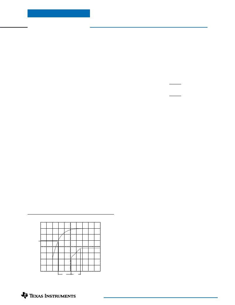
�Figure� 1-1� shows� the� power-up� characteristic� of� a� PT5404�
�(1.8� V).� In� this� example� the� delay� time,� t� d� ,� is� measured�
�from� the� point� at� which� the� input� voltage� rises� above�
�2.95� V� (the� UVLO� threshold),� to� the� point� that� the� output�
�voltage� starts� to� rise.� The� time� period� t� (SS)� is� the� rise� time�
�of� the� output� voltage� ramp.� The� value� of� t� d� and� t� (SS)�
�are� are� approximately� 10� ms� and� 7.5� ms� respectively.�
�Figure� 1-1;� Soft-Start� Characteristic� and� Timing�
�HORIZ� SCALE:� 5ms/Div�
�Vin� (1V/Div)�
�Vin� =2.95V�
�Vout� (1V/Div)�
�Note:� The� capacitor� should� be� placed� as� close� to� the� regulator� as�
�possible.� Adding� 0.047� μF� of� external� capacitance� to� the� Inhibit�
�pin� approximately� doubles� the� value� of� t� d� and� t� (SS)� .�
�Current� Limit� Protection�
�The� output� current� limit� feature� is� one� of� two� fault�
�protection� mechanisms� built� into� the� PT5400� modules.�
�Its� purpose� is� to� protect� both� the� module� and� input� source�
�against� the� occurance� of� a� load� fault,� thereby� isolating� the�
�fault� and� preventing� it� from� propagating� to� other� parts�
�of� the� power� system.� The� PT5400� regulators� sense� the�
�current� switched� by� the� series� (high-side)� power� MOSFET.�
�The� circuit� implements� a� continuous� current� limit� char-�
�acteristic.� Upon� the� removal� of� the� fault� the� output� voltage�
�will� promptly� recover,� and� the� module� will� return� to� nor-�
�mal� operation.�
�A� current� limit� condition� will� also� increase� the� module’s�
�power� dissipation,� which� may� cause� the� temperature� of�
�the� internal� components� to� significantly� rise.� If� the� con-�
�dition� persists,� the� module� may� begin� to� cycle� in� and� out�
�of� thermal� shutdown.�
�Thermal� Shutdown�
�Thermal� shutdown� is� the� second� fault� protection� mecha-�
�nism� and� protects� the� module’s� internal� circuitry� against�
�excessively� high� temperatures.� A� rise� in� the� temperature�
�of� the� internal� circuitry� may� be� the� result� of� a� drop� in�
�airflow,� a� high� ambient� temperature,� or� a� sustained� over-�
�current� load� fault.� If� the� junction� temperature� of� the�
�internal� components� exceed� 150� °C,� the� module� will�
�shutdown.� Once� in� thermal� shutdown,� the� regulator� is�
�disabled� and� the� output� voltage� is� reduced� to� zero.� The�
�recovery� is� automatic� and� begins� with� a� soft-start� power�
�up.� Recovery� occurs� when� the� the� sensed� temperature�
�decreases� 10� °C� below� the� trip� point.�
�t� d�
�t� (SS)�
�For� technical� support� and� further� information,� visit� http://power.ti.com�
�相关PDF资料 |
PDF描述 |
|---|---|
| AISM-1210-3R9K-T | INDUCTOR 3.9UH 10% 1210 |
| GSM43DRYF | CONN EDGECARD 86POS DIP .156 SLD |
| AISC-0603-R0047J-T | INDUCTOR WW CERAM 4.7NH 0603 |
| S1A-E3/5AT | DIODE GPP 1A 50V SMA DO-214AC |
| GMM43DRYF | CONN EDGECARD 86POS DIP .156 SLD |
相关代理商/技术参数 |
参数描述 |
|---|---|
| PT5404N | 功能描述:DC/DC转换器 1.8V 6A 3.3/5V Input Adj SWIFT Module RoHS:否 制造商:Murata 产品: 输出功率: 输入电压范围:3.6 V to 5.5 V 输入电压(标称): 输出端数量:1 输出电压(通道 1):3.3 V 输出电流(通道 1):600 mA 输出电压(通道 2): 输出电流(通道 2): 安装风格:SMD/SMT 封装 / 箱体尺寸: |
| PT5405 | 制造商:TI 制造商全称:Texas Instruments 功能描述:6-A 5-V/3.3-V Input Adjustable SWIFT Power Module |
| PT5405A | 功能描述:DC/DC转换器 6A 5/3.3V IN/1.5VOUT RoHS:否 制造商:Murata 产品: 输出功率: 输入电压范围:3.6 V to 5.5 V 输入电压(标称): 输出端数量:1 输出电压(通道 1):3.3 V 输出电流(通道 1):600 mA 输出电压(通道 2): 输出电流(通道 2): 安装风格:SMD/SMT 封装 / 箱体尺寸: |
| PT5405C | 功能描述:DC/DC转换器 1.5V 6A 3.3/5V Input Adj SWIFT Module RoHS:否 制造商:Murata 产品: 输出功率: 输入电压范围:3.6 V to 5.5 V 输入电压(标称): 输出端数量:1 输出电压(通道 1):3.3 V 输出电流(通道 1):600 mA 输出电压(通道 2): 输出电流(通道 2): 安装风格:SMD/SMT 封装 / 箱体尺寸: |
| PT5405N | 功能描述:DC/DC转换器 1.5V 6A 3.3/5V Input Adj SWIFT Module RoHS:否 制造商:Murata 产品: 输出功率: 输入电压范围:3.6 V to 5.5 V 输入电压(标称): 输出端数量:1 输出电压(通道 1):3.3 V 输出电流(通道 1):600 mA 输出电压(通道 2): 输出电流(通道 2): 安装风格:SMD/SMT 封装 / 箱体尺寸: |
发布紧急采购,3分钟左右您将得到回复。