- 您现在的位置:买卖IC网 > PDF目录358291 > PT6440 (Texas Instruments, Inc.) 6A Adjustable Step-Down ISR Family PDF资料下载
参数资料
| 型号: | PT6440 |
| 厂商: | Texas Instruments, Inc. |
| 英文描述: | 6A Adjustable Step-Down ISR Family |
| 中文描述: | 6A 可调节步降 ISR 系列 |
| 文件页数: | 4/8页 |
| 文件大小: | 178K |
| 代理商: | PT6440 |
For technical support and more information, see inside back cover or visit www.ti.com
Application Notes
Capacitor Recommendations for the PT6440
Excalibur 5V/3.3V Bus Step-Down ISRs
Input Capacitors
The recommended input capacitance is determined by
350 milli-amperes (rms) minimum ripple current rating
and 100μF minimum capacitance. Capacitors placed at
the input must be rated for a minimum of twice the input
voltage with +5V operation. Ripple current and
≤
200m
Equivalent Series Resistance (ESR) values are the major
considerations, along with temperature, when selecting
the proper input capacitor.
Output Capacitors
The ESR of the required 330μF output capacitor must
be less than or equal to 100m
. Failure to observe this
requirement may lead to regulator instability or oscillation.
Electrolytic capacitors have poor ripple performance at
frequencies greater than 300kHz but excellent low fre-
quency transient response. Above the ripple frequency,
ceramic decoupling capacitors are necessary to improve the
transient response and reduce any high frequency noise
components apparent during higher current excursions.
The preferred low ESR type capacitor part numbers are
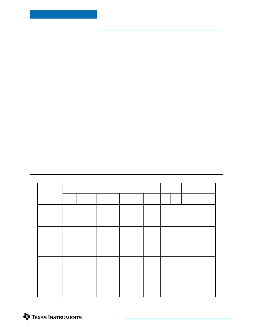
identified in Table 1.
Tanatalum Capacitors
Tantalum capacitors are recommended on the output bus
but only the AVX TPS series, Sprague 593D/594/595
series or Kemet T495/T510 series. These capacitors are
specified over many other types due to their higher surge
current, power dissipation and ripple current capability.
As a caution, the TAJ Series by AVX is not recommended.
This series exhibits considerably higher ESR and lower
ripple current capability. The TAJ series is also less reliable
than the TPS series when determining power dissipation
capability. Tantalum or Oscon types are recommended
in applications where ambient temperatures fall below 0°C.
Capacitor Table
Table 1 identifies vendors with acceptable ESR and
maximum allowable ripple current (rms) ratings. The
suggested minimum quantities per regulator for both
the input and output buses are identified.
This is not an extensive capacitor list. Capacitors from other
vendors are available with comparable specifications. Those
listed are for guidance. The RMS ripple current rating and
ESR (Equivalent Series Resistance at 100kHz) are critical
parameters necessary to insure both optimum regulator perfor-
mance and long capacitor life.
PT6440 Series
/
d
n
e
V
t
e
n
o
p
m
o
C
s
S
r
a
p
a
C
s
a
h
C
r
a
p
a
C
y
a
u
Q
g
e
n
W
a
V
g
)
μ
u
V
t
c
n
e
q
E
a
R
)
S
E
s
S
e
e
p
)
m
m
u
m
i
a
M
e
C
C
°
5
8
r
l
m
c
P
(
)
m
t
p
s
u
B
n
t
s
u
B
p
O
r
b
m
u
N
r
d
n
e
V
)
a
R
(
C
F
,
o
n
a
P
)
u
o
M
e
u
S
C
F
V
V
V
5
5
5
3
3
2
V
V
V
6
5
5
1
2
3
F
F
F
μ
μ
μ
0
0
0
9
0
3
3
1
3
F
F
F
μ
μ
μ
0
0
0
2
0
3
2
1
3
5
7
0
6
1
9
0
1
0
5
1
4
0
÷
2
0
5
6
A
A
A
m
m
5
5
5
5
5
7
5
0
2
1
m
A
A
A
m
m
m
5
0
2
1
0
0
7
5
6
4
5
1
8
×
0
1
×
×
5
1
5
1
5
1
0
1
×
8
×
2
1
×
2
1
2
1
5
1
1
1
1
1
1
1
1
/
1
R
N
2
/
1
R
N
S
1
1
1
9
0
3
3
1
3
V
V
E
1
1
1
C
C
C
F
F
F
U
U
U
E
E
E
E
E
E
P
1
P
1
7
4
V
1
C
F
V
E
E
2
1
2
0
C
1
1
1
C
C
F
F
V
V
E
E
E
E
Q
L
n
o
C
-
m
e
h
Z
C
X
d
L
/
e
U
X
L
V
S
F
V
V
5
5
2
3
V
V
0
0
1
1
F
F
μ
μ
0
0
3
2
3
2
F
F
μ
μ
0
0
3
0
3
1
4
2
8
0
0
0
÷
9
5
0
2
4
0
0
A
A
m
m
5
0
2
6
8
7
A
A
m
m
0
0
0
0
5
1
3
2
0
1
×
6
0
1
×
1
5
1
0
1
×
3
×
8
5
1
1
1
1
1
1
2
1
/
R
N
L
L
L
L
6
2
1
1
X
X
0
0
1
1
M
M
1
2
2
B
V
5
3
Z
X
L
1
3
3
B
V
5
2
V
X
L
M
M
0
0
3
0
3
1
S
S
F
F
0
0
1
1
)
a
R
(
L
P
,
o
c
c
N
)
u
o
M
e
u
S
D
U
V
5
3
V
V
5
5
3
3
F
μ
0
3
3
F
F
μ
μ
0
0
3
2
3
2
5
6
0
0
2
9
7
0
1
÷
A
m
0
2
0
1
A
A
m
m
0
0
7
5
6
4
5
1
×
5
1
0
1
×
0
8
×
0
1
1
1
1
1
1
1
2
6
H
H
M
1
3
3
V
1
L
P
U
S
G
1
1
R
R
N
N
M
1
1
2
2
V
1
D
U
U
M
1
3
3
V
1
D
U
U
S
G
)
a
R
(
S
S
,
o
c
O
)
u
o
M
e
u
S
V
S
V
0
1
V
V
0
6
1
1
F
μ
0
3
3
F
F
μ
μ
0
0
3
0
3
1
5
2
0
5
5
2
4
0
0
A
m
0
0
5
3
>
A
A
m
m
0
0
2
2
0
0
8
3
>
0
1
×
5
1
3
1
3
1
×
×
3
1
3
1
1
1
1
1
1
/
R
N
M
0
3
3
S
S
0
1
M
M
0
0
0
0
3
1
V
V
S
S
0
6
1
1
S
P
T
m
u
a
T
X
V
A
V
V
V
0
0
0
1
1
1
F
F
F
μ
μ
μ
0
0
0
3
3
5
3
3
1
0
0
0
0
6
0
1
0
1
A
A
A
m
m
m
4
6
5
1
2
9
4
8
0
1
1
1
L
W
H
3
×
3
×
1
1
1
1
1
1
2
0
0
0
6
0
1
0
0
0
0
1
R
R
R
0
0
0
1
1
1
0
0
0
M
M
M
7
0
1
D
S
P
T
7
7
3
3
3
3
V
V
S
S
P
P
T
T
0
1
5
T
,
m
e
K
9
4
T
5
V
V
0
0
1
1
F
F
μ
μ
0
0
3
2
3
2
3
2
3
0
0
0
÷
7
A
A
m
m
0
0
0
2
>
0
0
4
1
L
×
3
×
W
7
H
0
1
1
1
2
S
S
A
A
0
0
1
1
0
0
M
M
7
7
3
2
3
2
X
X
0
5
1
9
5
4
T
T
e
u
g
a
p
S
9
5
D
4
V
V
0
0
1
1
F
F
μ
μ
0
0
3
5
3
1
5
0
4
9
0
0
A
A
m
m
0
0
5
0
3
1
2
1
L
1
3
×
W
6
H
×
1
1
1
2
T
T
2
2
R
C
0
0
1
1
0
0
0
0
X
X
7
7
3
5
3
1
D
D
4
4
9
9
5
5
Table 1; Input/Output Capacitors
相关PDF资料 |
PDF描述 |
|---|---|
| PTHF10-121H | 1 ELEMENT, 10 uH, FERROUS ALLOY-CORE, GENERAL PURPOSE INDUCTOR |
| PTHF330-50H | 1 ELEMENT, 330 uH, FERROUS ALLOY-CORE, GENERAL PURPOSE INDUCTOR |
| PTKM150-50H | 1 ELEMENT, 150 uH, FERROUS ALLOY-CORE, GENERAL PURPOSE INDUCTOR |
| PTT-118-04-L-5 | 90 CONTACT(S), MALE, STRAIGHT TWO PART BOARD CONNECTOR, PRESS FIT |
| PTT-118-04-L-6 | 108 CONTACT(S), MALE, STRAIGHT TWO PART BOARD CONNECTOR, PRESS FIT |
相关代理商/技术参数 |
参数描述 |
|---|---|
| PT6441 | 制造商:TI 制造商全称:Texas Instruments 功能描述:6-A 5-V/3.3-V Input Adjustable Integrated Switching Regulator |
| PT6441A | 功能描述:DC/DC转换器 3.3Vout 6A 5V-Inp Adj Step-Down ISR RoHS:否 制造商:Murata 产品: 输出功率: 输入电压范围:3.6 V to 5.5 V 输入电压(标称): 输出端数量:1 输出电压(通道 1):3.3 V 输出电流(通道 1):600 mA 输出电压(通道 2): 输出电流(通道 2): 安装风格:SMD/SMT 封装 / 箱体尺寸: |
| PT6441C | 功能描述:DC/DC转换器 3.3Vout 6A 5V-Inp Adj Step-Down ISR RoHS:否 制造商:Murata 产品: 输出功率: 输入电压范围:3.6 V to 5.5 V 输入电压(标称): 输出端数量:1 输出电压(通道 1):3.3 V 输出电流(通道 1):600 mA 输出电压(通道 2): 输出电流(通道 2): 安装风格:SMD/SMT 封装 / 箱体尺寸: |
| PT6441N | 功能描述:DC/DC转换器 3.3Vout 6A 5V-Inp Adj Step-Down ISR RoHS:否 制造商:Murata 产品: 输出功率: 输入电压范围:3.6 V to 5.5 V 输入电压(标称): 输出端数量:1 输出电压(通道 1):3.3 V 输出电流(通道 1):600 mA 输出电压(通道 2): 输出电流(通道 2): 安装风格:SMD/SMT 封装 / 箱体尺寸: |
| PT6442 | 制造商:TI 制造商全称:Texas Instruments 功能描述:6-A 5-V/3.3-V Input Adjustable Integrated Switching Regulator |
发布紧急采购,3分钟左右您将得到回复。