- 您现在的位置:买卖IC网 > PDF目录66054 > PT6684E (TEXAS INSTRUMENTS INC) 5 A SWITCHING REGULATOR, 600 kHz SWITCHING FREQ-MAX, SMA14 PDF资料下载
参数资料
| 型号: | PT6684E |
| 厂商: | TEXAS INSTRUMENTS INC |
| 元件分类: | 稳压器 |
| 英文描述: | 5 A SWITCHING REGULATOR, 600 kHz SWITCHING FREQ-MAX, SMA14 |
| 封装: | SMD-14 |
| 文件页数: | 1/7页 |
| 文件大小: | 150K |
| 代理商: | PT6684E |
For technical support and more information, see inside back cover or visit www.ti.com/powertrends
Single Device: 5A Output
Input Voltage Range: 18V to 36V
Adjustable Output Voltage
80% Efficiency
Remote Sense Capability
Standby Function
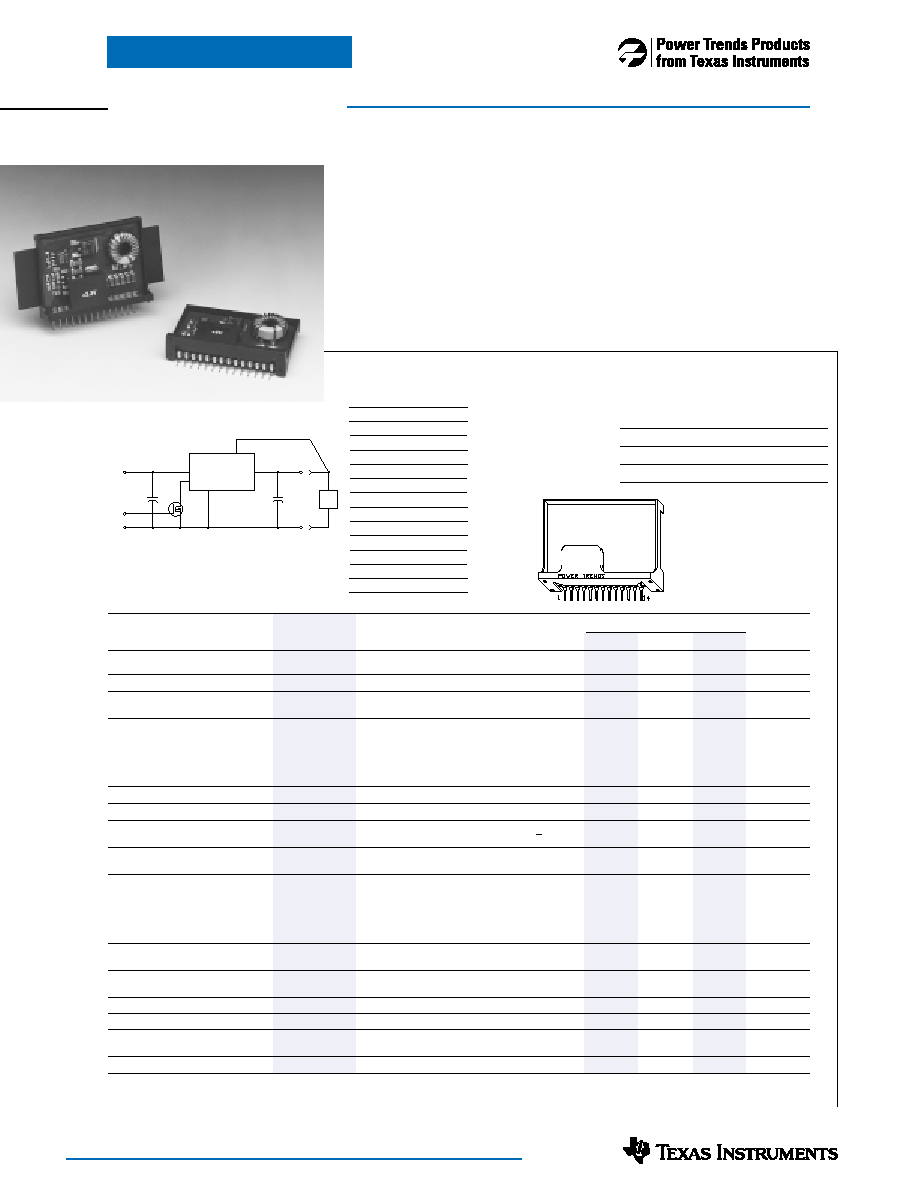
The PT6680 series is a new addi-
tion to Power Trends’ line of 24V bus
Integrated Switching Regulators (ISRs).
Designed for general purpose indus-
5 Amp 18-36V Input
Integrated Switching Regulator
PT6680 Series
Standard Application
C1 = Required 560F electrolytic (1)
C2 = Required 330F electrolytic
Q1= NFET-or Open Collector Gate
PT6680
4,5,6
7,8,9,10
11,12,13
V
IN
COM
V
OUT
C
2
+
C
1
+
1
3
STBY
Q
1
REMOTE SENSE
LOAD
Ordering Information
PT6681! = +3.3 Volts
PT6682! = +2.5 Volts
PT6683! = +5.0 Volts
PT6684! = +9.0 Volts
PT6685! = +15.0 Volts
PT6686! = +12.0 Volts
PT Series Suffix (PT1234X)
Case/Pin
Heat
Heat Spreader
Configuration
Spreader with Side Tabs
Vertical Through-Hole
PR
Horizontal Through-Hole DG
Horizontal Surface Mount EB
1
Remote Sense
2
Do Not Connect
3
STBY*- Standby
4Vin
5Vin
6Vin
7
GND
8
GND
9
GND
10GND
11
Vout
12
Vout
13
Vout
14
Vout Adjust
Pin-Out Information
trial applications requiring as much as
36V input and 5A of output current,
the PT6680 is packaged in a 14-Pin
SIP (Single In-line Package) and is
available in a surface-mount configu-
ration.
Only two external capacitors are
required for proper operation. Please
note that this product does not include
short circuit protection.
Note: Back surface
of product is
conducting metal
Pkg Style 400
Specifications
Characteristics
PT6680 SERIES
(T
a = 25°C unless noted)
Symbols
Conditions
Min
Typ
Max
Units
Output Current
Io
Ta = 60°C, 200 LFM, pkg P
0.1 (2)
—
5.0
A
Ta = 25°C, natural convection
0.1 (2)
—
5.0
Input Voltage Range
Vin
0.1A
≤ Io ≤ Iomax
+18V
—
+36V
V
Output Voltage Tolerance
Vo
Over Vin range
Ta = -40°C to +65°C
Vo-0.1
—
Vo+0.1
V
Output Voltage Adjust Range
Voadj
Pin 14 to Vo or ground
Vo = +3.3V
2.2
—
4.7
Vo = +2.5V
1.8
—
4.3
Vo = +5.0V
3.0
—
6.5
V
Vo = +9.0V
6.0
—
10.2
Vo = +12V
9.0—
13.6
Vo = +15V
10.0
—
17.0
Line Regulation
Regline
+18V
≤Vin≤+36V, Io = Iomax
—
±0.5
±1.0
%Vo
Load Regulation
Regload
Vin = +28V, 0.1≤ Io≤ Iomax
—
±0.5
±1.0
%Vo
Vo Ripple/Noise
Vn
Vin = +28V, Io = Iomax
Vo < +6V
—
50—
mVpp
Vo > +6V
1.0%Vo
Transient Response
ttr
Io step between 2.5A and 5.0A
—
100
—
Sec
with C2 = 330F
Vos
Vo over/undershoot
—
100
—
mV
Efficiency
η
Vin = +28V, Io = Io max
Vo = +3.3V
—
78
—
Vo = +2.5V
—
73
—
Vo = +5.0V
—
82
—
%
Vo = +9.0V
—
87
—
Vo = +12.0V
—
88
—
Vo = +15.0V
—
90
—
Switching Frequency
o
+18V
≤ Vin ≤ +36V
50
055060
0kHz
Over Io range
Maximum Operating
Ta
Over Vin range
-40—
+85 (3)
°C
Temperature Range
Storage Temperature
Ts
—
-40—
+125
°C
Mechanical Shock
—
Per Mil-STD-883D, Method 2002.3
—
500
—
G’s
Mechanical Vibration
—
Per Mil-STD-883D, Method 2007.2,
—
7.5
—
G’s
20-2000 Hz, soldered in a PC board
Weight
—
14
—
grams
Notes (1) The 560F electrolytic input capacitor must be rated for 1.5Arms ripple current. Both an input and output capacitor is required for proper operation.
(2) The ISR will operate down to no load with reduced specifications.
(3) Consult the SOA curves or contact the factory to determine the appropriate derating.
SLTS098
(Revised 6/30/2000)
PT6680
相关PDF资料 |
PDF描述 |
|---|---|
| PT6682P | 5 A SWITCHING REGULATOR, 600 kHz SWITCHING FREQ-MAX, SMA14 |
| PT6682E | 5 A SWITCHING REGULATOR, 600 kHz SWITCHING FREQ-MAX, SMA14 |
| PT6682G | 5 A SWITCHING REGULATOR, 600 kHz SWITCHING FREQ-MAX, SMA14 |
| PT6682B | 5 A SWITCHING REGULATOR, 600 kHz SWITCHING FREQ-MAX, SMA14 |
| PT6684P | 5 A SWITCHING REGULATOR, 600 kHz SWITCHING FREQ-MAX, SMA14 |
相关代理商/技术参数 |
参数描述 |
|---|---|
| PT6684G | 制造商:TI 制造商全称:Texas Instruments 功能描述:5 Amp 18-36V Input Integrated Switching Regulator |
| PT6684P | 制造商:TI 制造商全称:Texas Instruments 功能描述:5 Amp 18-36V Input Integrated Switching Regulator |
| PT6684R | 功能描述:REGULATOR 9V 5A VERT W/TABS RoHS:否 类别:电源 - 板载 >> DC DC Converters 系列:PT6680 标准包装:10 系列:PT4570 类型:隔离 输出数:1 电压 - 输入(最小):36V 电压 - 输入(最大):75V Voltage - Output 1:9V Voltage - Output 2:- Voltage - Output 3:- 电流 - 输出(最大):3.3A 电源(瓦) - 制造商系列:30W 电压 - 隔离:1.5kV(1500V) 特点:- 安装类型:表面贴装 封装/外壳:19-SIP SMD 模块 尺寸/尺寸:3.00" L x 1.19" W x 0.50" H(76.2mm x 30.2mm x 12.7mm) 包装:托盘 工作温度:-40°C ~ 85°C 效率:84% 电源(瓦特)- 最大:30W |
| PT6685 | 制造商:未知厂家 制造商全称:未知厂家 功能描述:15Vout 5 Amp 18-36V Input Adjustable Integrated Switching Regulator |
| PT6685B | 制造商:TI 制造商全称:Texas Instruments 功能描述:5 Amp 18-36V Input Integrated Switching Regulator |
发布紧急采购,3分钟左右您将得到回复。