- 您现在的位置:买卖IC网 > PDF目录96795 > PT6722A (TEXAS INSTRUMENTS INC) 14 A SWITCHING REGULATOR, 400 kHz SWITCHING FREQ-MAX, SMA23 PDF资料下载
参数资料
| 型号: | PT6722A |
| 厂商: | TEXAS INSTRUMENTS INC |
| 元件分类: | 稳压器 |
| 英文描述: | 14 A SWITCHING REGULATOR, 400 kHz SWITCHING FREQ-MAX, SMA23 |
| 封装: | ROHS COMPLIANT, SIP-23 |
| 文件页数: | 4/8页 |
| 文件大小: | 179K |
| 代理商: | PT6722A |
For technical support and more information, see inside back cover or visit www.ti.com
Application Notes
Operating Features of the Programmable
PT6700 “Excalibur” Series ISRs
Power Good
Programmable versions of the PT6700 Series regulators
incorporate a PWR Good output (pin 2). This output is
open-drain and generates an acitve-high signal when the
sensed output from the ISR is within a nominal ±10% of
the programmed set point. When the regulated output is
outside this range, pin 2 asserts a logic low (typically <0.1V). A
10-k
pull-up resistor to a valid bus voltage is required.
If the power good feature is not used, the pull-up resistor
can be omitted. The maximum voltage that may be ap-
plied to the pull-up resistor is 15V.
Over-Voltage Protection (OVP)
The PT6700 programmable regulators also incorporate
an OVP function. The OVP DRV (pin 1) normally has a
logic low output (typically <0.1V). When the ISR’s sensed
output exceeds the programmed output setting by 15%,
pin 1 produces a 60mA, +12V drive signal. This drive
signal can trigger an SCR, which can be used to disable
the input voltage (via a fuse), or alternatively interface to
another external monitoring device. When the ISR output
voltage returns to within 15% of its programmed setting,
pin 1 reverts back to its low state. If the OVP function is
not used, pin 1 may be left open circuit.
Stand-By Function
The PT6700 series ISRs incorporate a standby function.
This feature may be used for power-up sequencing, or
wherever there is a requirement for the output voltage
to be controlled by external circuitry.
If the STBY* input (pin 8) is left open-circuit the regulator
operates normally, providing a regulated output when a
valid supply voltage is applied to Vin (pins 10-12) with
respect to GND (pins 14-18). Connecting pin 8 to ground1
places the regulator in standby mode 2, and reduces the input
current to typically 20mA (30mA max). Applying a ground
signal to pin 8 prior to power-up, will disable the output
during the period that input power is applied. To ensure
that the regulator output is properly enabled, pin 8 must
be open circuit.
Table 1 Standby Control Requirements 2
Parameter
Min
Typ
Max
Enable
Open Cct. 1
Disable
-0.1V
0.4V
1.0V
Istby
10A
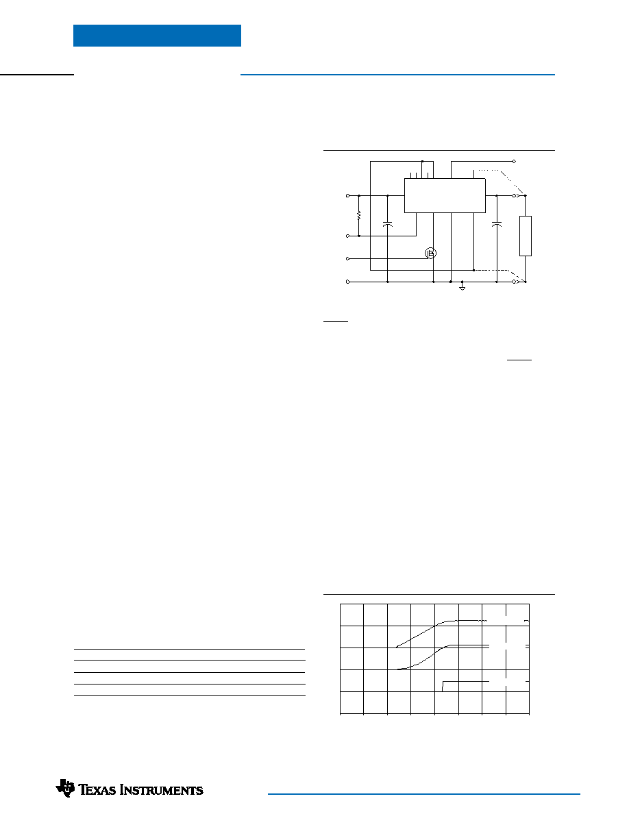
Figure 1
Figure 2
C
out
+
C
in
+
5V
COM
Inhibit
L
O
A
D
V
o
=2.5V
COM
Q1
BSS138
PT6700
76
543
2 3
19-22
13
8
14-18
2
10-12
Vo
Vin
GND
SNS(+)
SNS(-)
Pwr
Good
STBY
VID4 - VID0
1
OVP
R1
10k
OVP DRV
Pwr
Good
PT6701/6702/6703, & PT6721/6722
0
5
10
15
20
25
30
35
40
t (milli - secs)
Iin (5A/Div)
Vout (2V/Div)
VPWGD (10V/Div)
Notes:
1. The standby on a PT6700 series regulator must be controlled
with an open-drain low-leakage (<100nA) MOSFET (See
fig. 1). Table 1 gives the threshold requirements. Do Not use a
pull-up resistor. The control input has an open-circuitvoltageof
between 4Vdc and 5Vdc. To set the regulator output to zero,
the control pin must be “pulled” to less than 1.0Vdc by sinking
current to ground.
2. When placed in the standby mode, the regulator output may
assert a low impedance to ground. If an external voltage is
applied to the output, it will sink current and possibly over-
stress the part.
Turn-On Time
Turning Q1 in Figure 1 off, removes the low-voltage signal
at pin 8. After a 10-15ms delay the regulator output
rises and reaches full output voltage within 30ms. Fig. 2
shows the typical waveforms of a PT6701 following the
prompt turn-off of Q1 at time t =0 secs. The output volt-
age was set to 2.5V, and the waveforms were measured
with a 5V input source, and 10A resistive load.
相关PDF资料 |
PDF描述 |
|---|---|
| PT6722N | 14 A SWITCHING REGULATOR, 400 kHz SWITCHING FREQ-MAX, SMA27 |
| PT6722C | 14 A SWITCHING REGULATOR, 400 kHz SWITCHING FREQ-MAX, SMA27 |
| PT6727N | 13 A SWITCHING REGULATOR, 400 kHz SWITCHING FREQ-MAX, SMA17 |
| PT6724C | 14 A SWITCHING REGULATOR, 400 kHz SWITCHING FREQ-MAX, SMA17 |
| PT6729N | 13 A SWITCHING REGULATOR, 400 kHz SWITCHING FREQ-MAX, SMA17 |
相关代理商/技术参数 |
参数描述 |
|---|---|
| PT6722C | 功能描述:REG 1.1-1.85V 13A 12VIN SMD RoHS:否 类别:电源 - 板载 >> DC DC Converters 系列:PT6720 设计资源:Maxi/Mini/Micro Design Guide, Appl Manual 标准包装:1 系列:Maxi 类型:隔离 输出数:1 电压 - 输入(最小):43V 电压 - 输入(最大):110V Voltage - Output 1:15V Voltage - Output 2:- Voltage - Output 3:- 电流 - 输出(最大):* 电源(瓦) - 制造商系列:400W 电压 - 隔离:* 特点:* 安装类型:通孔 封装/外壳:模块 尺寸/尺寸:4.60" L x 2.20" W x 0.54" H(116.8mm x 55.9mm x 13.7mm) 包装:散装 工作温度:-55°C ~ 100°C 效率:* 电源(瓦特)- 最大:* |
| PT6722N | 功能描述:REG 1.1-1.85V 13A 12VIN VERT RoHS:否 类别:电源 - 板载 >> DC DC Converters 系列:PT6720 设计资源:Maxi/Mini/Micro Design Guide, Appl Manual 标准包装:1 系列:Maxi 类型:隔离 输出数:1 电压 - 输入(最小):43V 电压 - 输入(最大):110V Voltage - Output 1:15V Voltage - Output 2:- Voltage - Output 3:- 电流 - 输出(最大):* 电源(瓦) - 制造商系列:400W 电压 - 隔离:* 特点:* 安装类型:通孔 封装/外壳:模块 尺寸/尺寸:4.60" L x 2.20" W x 0.54" H(116.8mm x 55.9mm x 13.7mm) 包装:散装 工作温度:-55°C ~ 100°C 效率:* 电源(瓦特)- 最大:* |
| PT6724 | 制造商:TI 制造商全称:Texas Instruments 功能描述:14-A 12V-Input Adjustable Integrated Switching Regulator |
| PT6724A | 功能描述:开关变换器、稳压器与控制器 5Vout 13A 12V Input Adjustable ISR RoHS:否 制造商:Texas Instruments 输出电压:1.2 V to 10 V 输出电流:300 mA 输出功率: 输入电压:3 V to 17 V 开关频率:1 MHz 工作温度范围: 安装风格:SMD/SMT 封装 / 箱体:WSON-8 封装:Reel |
| PT6724C | 功能描述:开关变换器、稳压器与控制器 5Vout 13A 12V Input Adjustable ISR RoHS:否 制造商:Texas Instruments 输出电压:1.2 V to 10 V 输出电流:300 mA 输出功率: 输入电压:3 V to 17 V 开关频率:1 MHz 工作温度范围: 安装风格:SMD/SMT 封装 / 箱体:WSON-8 封装:Reel |
发布紧急采购,3分钟左右您将得到回复。