参数资料
| 型号: | PT7C4307WEX |
| 厂商: | Pericom |
| 文件页数: | 4/16页 |
| 文件大小: | 0K |
| 描述: | IC RTC ALARM NVSRAM 8SOIC |
| 标准包装: | 1 |
| 类型: | 时钟/日历 |
| 特点: | 警报器,闰年,NVSRAM,方波输出 |
| 存储容量: | 56B |
| 时间格式: | HH:MM:SS(12/24 小时) |
| 数据格式: | YY-MM-DD-dd |
| 接口: | I²C,2 线串口 |
| 电源电压: | 4.5 V ~ 5.5 V |
| 电压 - 电源,电池: | 2 V ~ 3.5 V |
| 工作温度: | -40°C ~ 85°C |
| 安装类型: | 表面贴装 |
| 封装/外壳: | 8-SOIC(0.154",3.90mm 宽) |
| 供应商设备封装: | 8-SOIC |
| 包装: | 标准包装 |
| 其它名称: | PT7C4307WEXDKR |
|||||||||||||||||||||||||||||||||||||||||||||||||||||||||||||||||||||||||||||||||||||||||||||||||||||||||||||||||||||||||||||||||||||||||||||||||||||||||||||||||||||||||||||||||||||||||||||||||||||||||||||||||||||||||||||||||||||||||||||||||||||||||||||||||||||||||||||||||||||||||||||||||||||||||||||||||||||||||||||||||||||||
PT0206(08/09)
Ver: 3
12
Data Sheet
PT7C4307
Real-time Clock Module (I
2C Bus)
Maximum Ratings
Storage Temperature......................................................................................................-65oCto +150oC
Ambient Temperature with Power Applied............................................................-40oCto +85oC
Supply Voltage to Ground Potential (Vcc to GND)............................................... -0.3V to +6.5V
DC Input (All Other Inputs except Vcc & GND)................................................... -0.3V to (Vcc+0.3V)
DC Output Voltage (SDA, /INTA, /INTB pins)..................................................... -0.3V to +6.5V
DC Output Current (FOUT)......................................................................................... -0.3V to (Vcc+0.3V)
Power Dissipation........................................................................................................320mW
(depend on package)
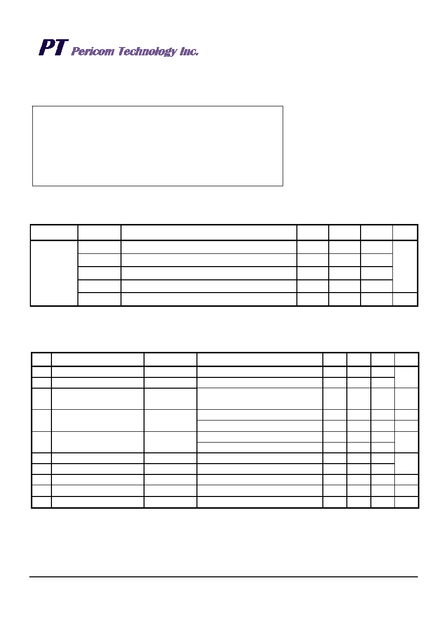
Recommended Operating Conditions
Part No.
Symbol
Description
Min
Type
Max
Unit
VCC
Power voltage
4.5
5
5.5
VBAT
Battery voltage
2
-
3.5
VIH
Input high level
2.2
-
VCC+0.3
VIL
Input low level
-0.3
-
0.8
V
PT7C4307
TA
Operating temperature
-40
-
85
C
DC Electrical Characteristics
Unless otherwise specified, VDD = 4.5 ~ 5.5 V, TA = -40 °C to +85 °C
Sym.
Item
Pin
Condition
Min
Typ
Max
Unit
VCC
Supply voltage
VCC
4.5
5.0
5.5
VBAT Supply voltage
VBATT
2.0
-
3.5
V
VPF
Power fail voltage
Note 4
1.216
×
VBAT
1.25
×
VBAT
1.284
×
VBAT
V
OSC on, Note 3
-
1.5
mA
ICC Current consumption
VCC
OSC off, Note 1
-
200
A
OSC on, SQW/OUT off, Note 2
-
300
500
IBAT Current consumption
VBAT
OSC on, SQW/OUT on (32kHz)
-
480
800
nA
VIL
Low-level input voltage
SCL
-
0.8
VIH
High-level input voltage
SCL
2.0
-
V
VOL
Low-level output voltage
SDA
IOL = 5mA
-
0.4
V
IIL
Input leakage current
SCL
-
1
A
IOZ
Output current when OFF
SDA
-
1
A
Note:
1.
VCC = 5.0V and SDA, SCL = 5.0V.
2.
VCC = 0V, VBAT = 3V.
3.
SCL clocking at max frequency = 100kHz. SDA pin open, /EOSC bit = 0 (oscillator enabled)
4.
VPF measured at VBAT = 3.0V.
Note:
Stresses
greater
than
those
listed
under
MAXIMUM RATINGS may cause permanent
damage to the device. This is a stress rating
only and functional operation of the device at
these or any other conditions above those
indicated in the operational sections of this
specification
is not implied.
Exposure to
absolute
maximum
rating
conditions
for
extended periods may affect reliability.
相关PDF资料 |
PDF描述 |
|---|---|
| PT7C4311WEX | IC RTC LEAP YEAR Y2K 8SOIC |
| PT7C43390WEX | IC REAL TIME CLOCK 8SOIC |
| PT7C4563UEX | IC REAL TIME CLOCK 8MSOP |
| QPI-12LZ-01 | IC INTERFACE FILTER |
| QPI-5LZ | FILTER 24V 14A ACTIVE EMI |
相关代理商/技术参数 |
参数描述 |
|---|---|
| PT7C4311WEX | 功能描述:IC RTC LEAP YEAR Y2K 8SOIC RoHS:是 类别:集成电路 (IC) >> 时钟/计时 - 实时时钟 系列:- 标准包装:2,500 系列:- 类型:时钟/日历 特点:警报器,闰年,监控器,监视计时器 存储容量:- 时间格式:HH:MM:SS(12/24 小时) 数据格式:YY-MM-DD-dd 接口:I²C,2 线串口 电源电压:2.7 V ~ 5.5 V 电压 - 电源,电池:1.8 V ~ 5.5 V 工作温度:-40°C ~ 85°C 安装类型:表面贴装 封装/外壳:14-TSSOP(0.173",4.40mm 宽) 供应商设备封装:14-TSSOP 包装:带卷 (TR) |
| PT7C4337 | 制造商:未知厂家 制造商全称:未知厂家 功能描述:Real-time Clock Module (I2C Bus) |
| PT7C4337PE | 制造商:未知厂家 制造商全称:未知厂家 功能描述:Real-time Clock Module (I2C Bus) |
| PT7C4337UE | 制造商:Pericom Semiconductor Corporation 功能描述: |
| PT7C4337WE | 制造商:Pericom Semiconductor Corporation 功能描述:1.8V - 5.5V, REA TIME CLOCK, 12C BUS, ALARM/CLOCK OUTPUT - Bulk |
发布紧急采购,3分钟左右您将得到回复。