- 您现在的位置:买卖IC网 > PDF目录98065 > PTH12040WAZ (TEXAS INSTRUMENTS INC) 1-OUTPUT DC-DC REG PWR SUPPLY MODULE PDF资料下载
参数资料
| 型号: | PTH12040WAZ |
| 厂商: | TEXAS INSTRUMENTS INC |
| 元件分类: | 电源模块 |
| 英文描述: | 1-OUTPUT DC-DC REG PWR SUPPLY MODULE |
| 封装: | ROHS COMPLIANT, DIP-20 |
| 文件页数: | 12/27页 |
| 文件大小: | 633K |
| 代理商: | PTH12040WAZ |
第1页第2页第3页第4页第5页第6页第7页第8页第9页第10页第11页当前第12页第13页第14页第15页第16页第17页第18页第19页第20页第21页第22页第23页第24页第25页第26页第27页
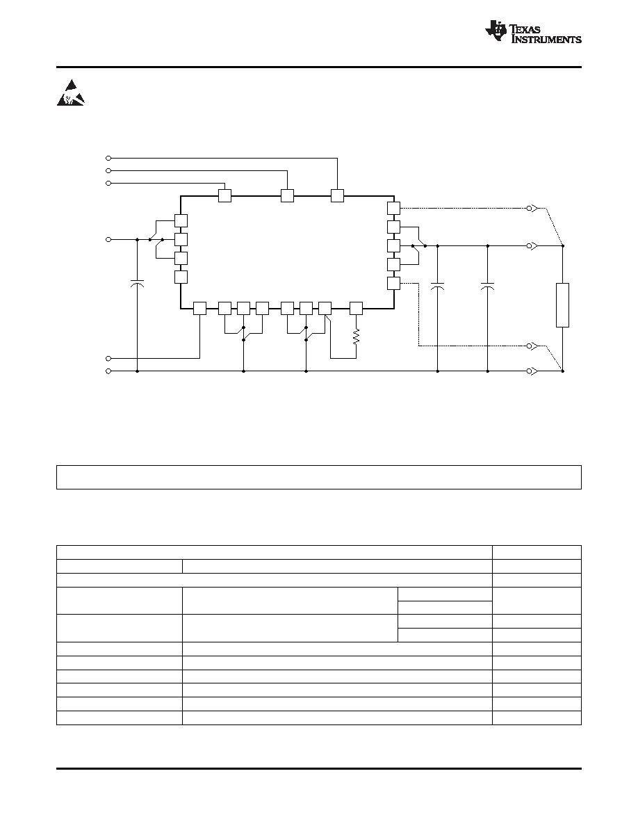
STANDARD APPLICATION
2
4
6
8
19
20
11
9
Margin Up
V
I
Track
+Sense
+
PTH12040W
V
I
V
I
UVLO Prog
Margin Down
18
Track
12
15
14
V
O
V
O
V
O
–Sense
7
1
Inhibit
17
GND
3
5
10
13
16
GNDGND
GND GND GND V
OAdjust
Track
Margin Up
Margin Down
C
I
560 mF
(Required)
R
SET
1%
0.05 W
L
O
A
D
+Sense
C
O1
330 mF
(Required)
C
O2
330 mF
(Required)
+
V
O
–Sense
GND
V
I
Inhibit
UDG-08112
ABSOLUTE MAXIMUM RATINGS
SLTS237G – DECEMBER 2004 – REVISED MARCH 2009............................................................................................................................................... www.ti.com
These devices have limited built-in ESD protection. The leads should be shorted together or the device placed in conductive foam
during storage or handling to prevent electrostatic damage to the MOS gates.
A.
RSET = Required to set the output voltage higher than the minimum value (see the elcetrical characheristics for
values.)
B.
CI = Required 560-F electrolytic capacitor. 1000 F recommended.
C.
CO = Required 660-F (or 680 F) electrolytic capacitor.
ORDERING INFORMATION
For the most current package and ordering information, see the Package Option Addendum at the end of this datasheet, or see
the TI website at www.ti.com.
over operating free-air temperature range (unless otherwise noted)
UNIT
Signal input voltages
Track control (pin 18)
–0.3 V to VI + 0.3 V
TA
Operating temperature range over VI range
–40°C to 85°C
PTH12040WAH
Wave solder
Surface temperature of module body or pins
Twave
260°C (1)
temperature
(5 seconds maximum)
PTH12040WAD
PTH12040WAS
235°C (1)
Solder reflow
Treflow
Surface temperature of module body or pins
temperature
PTH12040WAZ
260°C (1)
Tstg
Storage temperature
Storage temperature of module removed from shipping package
–55°C to 125°C
Tpkg
Packaging temperature
Shipping Tray storage or bake temperature
45°C
Mechanical shock
Per Mil-STD-883D, Method 2002.3, 1 msec, 1/2 Sine, mounted
500 G
Mechanical vibration
Mil-STD-883D, Method 2007.2, 20–2000 Hz
15 G
Weight
17 grams
Flammability
Meets UL94V-O
(1)
During the soldering process, do not elevate peak temperature of the module, pins, or internal components above the stated maximum.
2
Copyright 2004–2009, Texas Instruments Incorporated
Product Folder Link(s): PTH12040W
相关PDF资料 |
PDF描述 |
|---|---|
| PTN04050AAST | 1 A SWITCHING REGULATOR, 310 kHz SWITCHING FREQ-MAX, PDMA5 |
| PTN04050AAD | 1 A SWITCHING REGULATOR, 310 kHz SWITCHING FREQ-MAX, PDMA5 |
| PTN04050AAZT | 1 A SWITCHING REGULATOR, 310 kHz SWITCHING FREQ-MAX, PDMA5 |
| PTN04050AAZ | 1 A SWITCHING REGULATOR, 310 kHz SWITCHING FREQ-MAX, PDMA5 |
| PTN04050AAH | 1 A SWITCHING REGULATOR, 310 kHz SWITCHING FREQ-MAX, PDMA5 |
相关代理商/技术参数 |
参数描述 |
|---|---|
| PTH12040WAZT | 功能描述:DC/DC转换器 8.0-14Vin 5.5V 50A 2.045" x1.045"x0.357 RoHS:否 制造商:Murata 产品: 输出功率: 输入电压范围:3.6 V to 5.5 V 输入电压(标称): 输出端数量:1 输出电压(通道 1):3.3 V 输出电流(通道 1):600 mA 输出电压(通道 2): 输出电流(通道 2): 安装风格:SMD/SMT 封装 / 箱体尺寸: |
| PTH12045WAD | 制造商:Texas Instruments 功能描述: |
| PTH12045WAZ | 制造商:Texas Instruments 功能描述:- Rail/Tube |
| PTH12050 | 制造商:EMERSON-NETWORKPOWER 制造商全称:Emerson Network Power 功能描述:DC-DC CONVERTERS |
| PTH12050L | 制造商:EMERSON-NETWORKPOWER 制造商全称:Emerson Network Power 功能描述:12 Vin |
发布紧急采购,3分钟左右您将得到回复。