- 您现在的位置:买卖IC网 > PDF目录69257 > PTN78000HAZ (TEXAS INSTRUMENTS INC) 1-OUTPUT 22.5 W DC-DC REG PWR SUPPLY MODULE PDF资料下载
参数资料
| 型号: | PTN78000HAZ |
| 厂商: | TEXAS INSTRUMENTS INC |
| 元件分类: | 电源模块 |
| 英文描述: | 1-OUTPUT 22.5 W DC-DC REG PWR SUPPLY MODULE |
| 封装: | ROHS COMPLIANT, DIP-5 |
| 文件页数: | 2/25页 |
| 文件大小: | 668K |
| 代理商: | PTN78000HAZ |
APPLICATION INFORMATION
Adjusting the Output Voltage of the PTN78000 Wide-Output Adjust Power Modules
General
R
=54.9k
SET
W
1.25 V
V -V
O
min
-R
P
(1)
Input Voltage Considerations
SLTS230B – NOVEMBER 2004 – REVISED OCTOBER 2007 .......................................................................................................................................... www.ti.com
A resistor must be connected between the VO Adjust control (pin 4) and GND (pin 1) to set the output voltage.
The adjustment range is from 2.5 V to 12.6 V for PTN78000W. The adjustment range is from 11.85 V to 22 V for
PTN78000H. If pin 4 is left open, the output voltage defaults to the lowest value.
Table 2 gives the preferred value of the external resistor for several standard voltages, with the actual output
voltage that the value provides. For other output voltages, the value of the required resistor can be calculated
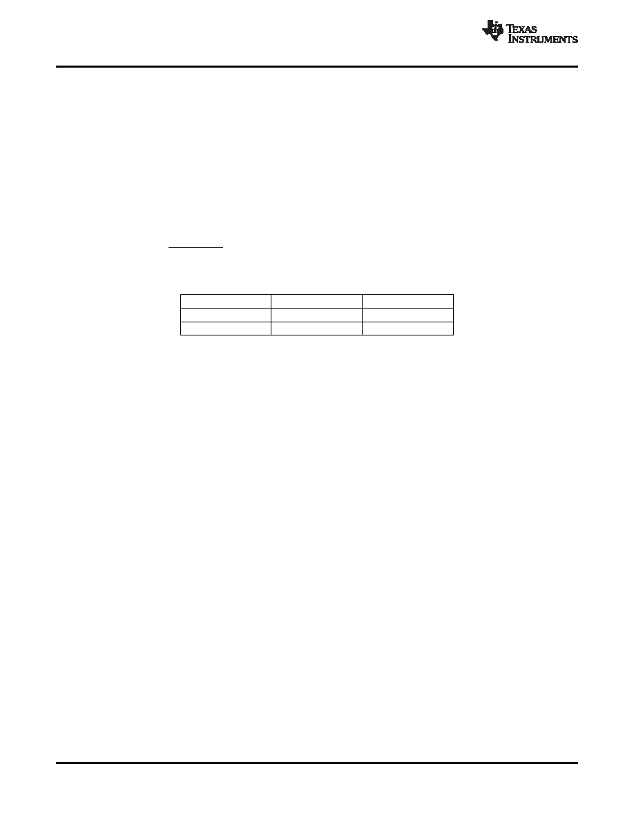
using Equation 1, and the constants for the applicable product in Table 1. Alternatilvey, RSET can be simply
selected from the range of values given in Table 3. Figure 27 shows the placement of the required resistor.
Table 1. RSET Formula Constants
PRODUCT
VMIN (V)
RP (k)
PTN780x0W
2.5
6.49
PTN780x0H
11.824
6.65
The PTN78000 is a step-down switching regulator. In order that the output remains in regulation, the input
voltage must exceed the output by a minimum differential voltage. (Please refer to the input voltage range
requirements in the electrical characteristics table.)
Another consideration is the pulse width modulation (PWM) range of the regulator's internal control circuit. For
stable operation, its operating duty cycle should not be lower than some minimum percentage. This defines the
maximum advisable ratio between the regulator input and output voltage magnitudes.
As an example, for satisfactory performance, the operating input voltage range of the PTN78000x must adhere to
the following requirements.
1. For PTN78000W output voltages lower than 10 V, the minimum input voltage is (VO + 2 V ) or 7 V, whichever
is higher.
2. For PTN78000W output voltages equal to 10 V and higher, the minimum input voltage is (VO + 2.5 V ) .
3. For PTN78000W, the maximum input voltage is (10 x VO ) or 36 V, whichever is less.
4. For PTN78000H output voltages lower than 19 V, the minimum input voltage is (VO + 3 V ) or 15 V,
whichever is higher.
5. For PTN78000H output voltages equal to 19 V and higher, the minimum input voltage is (VO + 4 V ) .
10
Copyright 2004–2007, Texas Instruments Incorporated
相关PDF资料 |
PDF描述 |
|---|---|
| PTN78000WAZT | 1-OUTPUT 22.5 W DC-DC REG PWR SUPPLY MODULE |
| PTN78000HAH | 1-OUTPUT 22.5 W DC-DC REG PWR SUPPLY MODULE |
| PTN78000WAZ | 1-OUTPUT 22.5 W DC-DC REG PWR SUPPLY MODULE |
| PTN78060AAZ | 1-OUTPUT 15 W DC-DC REG PWR SUPPLY MODULE |
| PTN78060AAST | 1-OUTPUT 15 W DC-DC REG PWR SUPPLY MODULE |
相关代理商/技术参数 |
参数描述 |
|---|---|
| PTN78000HAZT | 功能描述:DC/DC转换器 1.5 A Wide I/O Adj Module RoHS:否 制造商:Murata 产品: 输出功率: 输入电压范围:3.6 V to 5.5 V 输入电压(标称): 输出端数量:1 输出电压(通道 1):3.3 V 输出电流(通道 1):600 mA 输出电压(通道 2): 输出电流(通道 2): 安装风格:SMD/SMT 封装 / 箱体尺寸: |
| PTN78000W | 制造商:TI 制造商全称:Texas Instruments 功能描述:1.5-A, WIDE-INPUT ADJUSTABLE SWITCHING REGULATOR |
| PTN78000W_08 | 制造商:TI 制造商全称:Texas Instruments 功能描述:1.5-A, WIDE-INPUT ADJUSTABLE SWITCHING REGULATOR |
| PTN78000WAH | 功能描述:DC/DC转换器 ADJ SWITCHING REGULATOR RoHS:否 制造商:Murata 产品: 输出功率: 输入电压范围:3.6 V to 5.5 V 输入电压(标称): 输出端数量:1 输出电压(通道 1):3.3 V 输出电流(通道 1):600 mA 输出电压(通道 2): 输出电流(通道 2): 安装风格:SMD/SMT 封装 / 箱体尺寸: |
| PTN78000WAH | 制造商:Texas Instruments 功能描述:DC/DC CONVERTER |
发布紧急采购,3分钟左右您将得到回复。