- 您现在的位置:买卖IC网 > PDF目录69257 > PTN78060AAZT (TEXAS INSTRUMENTS INC) 1-OUTPUT 15 W DC-DC REG PWR SUPPLY MODULE PDF资料下载
参数资料
| 型号: | PTN78060AAZT |
| 厂商: | TEXAS INSTRUMENTS INC |
| 元件分类: | 电源模块 |
| 英文描述: | 1-OUTPUT 15 W DC-DC REG PWR SUPPLY MODULE |
| 封装: | ROHS COMPLIANT, DIP-7 |
| 文件页数: | 5/19页 |
| 文件大小: | 589K |
| 代理商: | PTN78060AAZT |
www.ti.com
Optional Input/Output Filters
Input/Output Capacitors
PTN78060A
2
1,7
+
4
Vo
GND
Adjust
Vo
6
GND
+
C1
4.7 mF
Ceramic
C2
100
F
Electrolytic
(Required)
C3(1)
3 y 4.7 mF
Ceramic
(Required)
RSET
C4 (2)
100
F
(Required)
C5
4.7
F
Ceramic
VI
UDG05092
C6
4.7
F
Ceramic
π Filters
SLTS245B – APRIL 2005 – REVISED AUGUST 2006
Power modules include internal input and output ceramic capacitors in all of their designs. However, some
applications require much lower levels of either input reflected or output ripple/noise. This application describes
various filters and design techniques found to be successful in reducing both input and output ripple/noise.
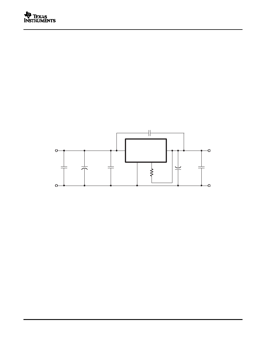
The easiest way to reduce output ripple and noise is to add one or more 1-F ceramic capacitors, such as C5
shown in Figure 20. Ceramic capacitors should be placed close to the output power terminals. A single 4.7-F
capacitor reduces the output ripple/noise by 10% to 30% for modules with a rated output current of less than 3
A. (Note: C4 is required to improve the regulators transient response, and does not reduce output ripple and
noise.)
Switching regulators draw current from the input line in pulses at their operating frequency. The amount of
reflected (input) ripple/noise generated is directly proportional to the equivalent source impedance of the power
source including the impedance of any input lines. The addition of C1,
≥4.7-F (2 ×2.2 F) ceramic capacitor,
near the input power pins, reduces reflected conducted ripple/noise by up to 20%.
(1)
See the specifications for required value and type.
(2)
See the Application Information section for suggested value and type.
Figure 20. Adding High-Frequency Bypass Capacitors to the Input and Output
If a further reduction in ripple/noise level is required for an application, higher order filters must be used. A
π (pi)
filter, employing a ferrite bead (Fair-Rite Pt. No. 2673000701 or equivalent) in series with the input or output
terminals of the regulator reduces the ripple/noise by at least 20 db (see Figure 21 and Figure 22). In order for
the inductor to be effective ceramic capacitors are also required. (See the Capacitor Recommendations for
additional information on vendors and component suggestions.)
These inductors plus ceramic capacitors form an excellent filter because of the rejection at the switching
frequency (650 kHz - 1 MHz). The placement of this filter is critical. It must be located as close as possible to the
input or output pins to be effective. The ferrite bead is small (12,5 mm × 3 mm), easy to use, low cost, and has
low dc resistance. Fair-Rite also manufactures a surface-mount bead (part number 2773021447). It is rated to 5
A, and can be used on the output bus. As an alternative, suitably rated 1-H to 5-H wound inductors can be
used in place of the ferrite inductor bead.
13
相关PDF资料 |
PDF描述 |
|---|---|
| PTN78060AAH | 1-OUTPUT 15 W DC-DC REG PWR SUPPLY MODULE |
| PTN78060WAZT | 1-OUTPUT 45 W DC-DC REG PWR SUPPLY MODULE |
| PTN78060HAST | 1-OUTPUT 45 W DC-DC REG PWR SUPPLY MODULE |
| PTN78060HAH | 1-OUTPUT 45 W DC-DC REG PWR SUPPLY MODULE |
| PTN78060WAZ | 1-OUTPUT 45 W DC-DC REG PWR SUPPLY MODULE |
相关代理商/技术参数 |
参数描述 |
|---|---|
| PTN78060AAZ-T | 制造商:TI 制造商全称:Texas Instruments 功能描述:15-W, WIDE-INPUT ADJUSTABLE POSITIVE-TO-NEGATIVE VOLTAGE REGULATOR MODULE |
| PTN78060H | 制造商:TI 制造商全称:Texas Instruments 功能描述:3-A, WIDE-INPUT ADJUSTABLE SWITCHING REGULATOR |
| PTN78060HAH | 功能描述:DC/DC转换器 3A Wide-In Wide Output Adj Module RoHS:否 制造商:Murata 产品: 输出功率: 输入电压范围:3.6 V to 5.5 V 输入电压(标称): 输出端数量:1 输出电压(通道 1):3.3 V 输出电流(通道 1):600 mA 输出电压(通道 2): 输出电流(通道 2): 安装风格:SMD/SMT 封装 / 箱体尺寸: |
| PTN78060HAH | 制造商:Texas Instruments 功能描述:ISR HORIZONTAL 3A ADJ O/P 78060 |
| PTN78060HAH | 制造商:Texas Instruments 功能描述:DC-DC CONV LINEAR REG 1 O/P 45W 3A 制造商:Texas Instruments 功能描述:DC-DC CONV, LINEAR REG, 1 O/P, 45W, 3A |
发布紧急采购,3分钟左右您将得到回复。