- 您现在的位置:买卖IC网 > PDF目录17494 > PV36W202C31A00 (Murata Electronics North America)TRIMMER 2K OHM 0.5W TH PDF资料下载
参数资料
| 型号: | PV36W202C31A00 |
| 厂商: | Murata Electronics North America |
| 文件页数: | 48/55页 |
| 文件大小: | 0K |
| 描述: | TRIMMER 2K OHM 0.5W TH |
| 标准包装: | 1,000 |
| 系列: | PV36 |
| 电阻(欧姆): | 2k |
| 功率(瓦特): | 0.5W,1/2W |
| 容差: | ±10% |
| 温度系数: | ±100ppm/°C |
| 匝数: | 25 |
| 调节型: | 顶部调节 |
| 电阻材料: | 金属陶瓷 |
| 安装类型: | 通孔 |
| 端接类型: | PC 引脚 |
| 包装: | 带盒(TB) |
| 尺寸/尺寸: | 方形 - 0.378" L x 0.197" W x 0.394" H(9.60mm x 5.00mm x 10.00mm) |
第1页第2页第3页第4页第5页第6页第7页第8页第9页第10页第11页第12页第13页第14页第15页第16页第17页第18页第19页第20页第21页第22页第23页第24页第25页第26页第27页第28页第29页第30页第31页第32页第33页第34页第35页第36页第37页第38页第39页第40页第41页第42页第43页第44页第45页第46页第47页当前第48页第49页第50页第51页第52页第53页第54页第55页
�� ��
��
��!� Note� ?� Please� read� rating� and� !� CAUTION� (for� storage,� operating,� rating,� soldering,� mounting� and� handling)� in� this� catalog� to� prevent� smoking� and/or� burning,� etc.�
�?� This� catalog� has� only� typical� speci?cations.� Therefore,� please� approve� our� product� speci?cations� or� transact� the� approval� sheet� for� product� speci?cations� before� ordering.�
�SMD Sealed Type (PVG3/M4A_D01/G5)/Lead Sealed Type (PV32/12/37/36) Speci?cations and Test Methods�
�The� following� describes� trimmer� potentiometer� testing� conducted� by� Murata� Manufacturing� Co.,� Ltd.� in� accordance� with� MIL-R-22097� (military� specification�
�for� variable� resistors,� non-wirewound)� and� MIL-STD-202� (test� methods� for� electronic� and� electrical� component� parts).�
�R50E.pdf�
�Jul.23,2012�
�No.�
�Item�
�Test� Methods�
�Measure� total� resistance� between� the� resistance� element� and� terminals� (#1� and� #3)� with� the� contact� arm� positioned�
�against� a� stop.� The� positioning� of� the� contact� arm� and� terminal� should� be� the� same� for� subsequent� total� resistance�
�measurements� on� the� same� device.� Use� the� test� voltage� specified� in� Table� 1� for� total� resistance� measurements.�
�This� voltage� should� be� used� for� all� subsequent� total� resistance� measurements.�
�Total� Resistance,�
�Maximum� Test�
�1�
�Total� Resistance�
�Nominal� (ohm)�
�10� V� R� V� 100�
�100� F� R� V� 1k�
�1k� F� R� V� 10k�
�10k� F� R� V� 100k�
�100k� F� R�
�Voltage� (V)�
�1.0�
�3.0�
�10.0�
�30.0�
�100.0�
�Table� 1:� Total� resistance� test� voltage�
�Position� the� contact� arm� at� the� extreme� counterclockwise� limit� of� mechanical� travel� and� measure� the� resistance�
�between� the� contact� arm� and� the� corresponding� end� terminal.� Then,� position� the� contact� arm� at� the� extreme�
�2�
�Residual� Resistance�
�clockwise� limit� of� mechanical� travel� and� measure� the� resistance� between� the� contact� arm� and� the� corresponding� end�
�terminal.� During� this� test,� take� suitable� precautions� to� ensure� that� the� rated� current� of� the� resistance� element� is� not�
�exceeded.�
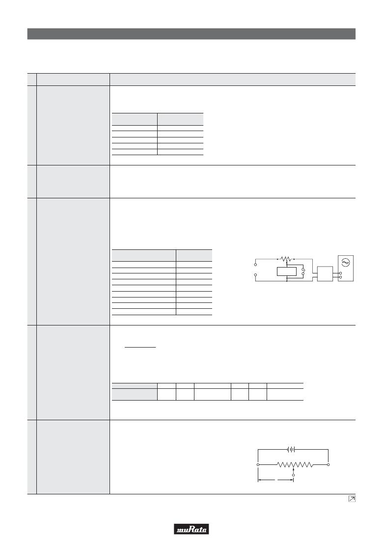
�Contact� resistance� variation� should� be� measured� with� the� measuring� circuit� shown� in� Figure� 1,� or� its� equivalent.� The�
�adjustment� rotor� (screw)� should� be� rotated� in� both� directions� through� 90%� of� the� actual� effective-electrical� rotational�
�angle� (number� of� turns)� for� a� total� of� 6� cycles.� Only� the� last� 3� cycles� should� count� in� determining� whether� or� not� a�
�contact� resistance� variation� is� observed� at� least� twice� in� the� same� location,� exclusive� of� the� roll-on� or� roll-off� points�
�where� the� contact� arm� moves� from� the� termination,� on� or� off,� the� resistance� element.� The� rate� of� rotation� of� the�
�adjustment� rotor� (screw)� should� be� such� that� the� adjustment� rotor� (screw)� completes� 1� cycle� for� 5� seconds� minimum�
�to� 2� minutes� maximum.� The� test� current� used� should� follow� the� value� given� in� Table� 2� unless� otherwise� limited� by�
�power� rating.�
�#� 3�
�#� 1�
�3�
�Contact� Resistance�
�Variation�
�Standard� Total� Resistance�
�R� (ohm)�
�R� V� 100�
�100� F� R� F� 500�
�500� V� R� F� 1k�
�1k� V� R� F� 2k�
�2k� V� R� F� 50k�
�50k� V� R� F� 200k�
�200k� V� R� F� 1M�
�1M� V� R� F� 2M�
�2M� V� R�
�Test� Current�
�20mA�
�10mA�
�4mA�
�2mA�
�1mA�
�200μA�
�100μA�
�50μA�
�30μA�
�Rx�
�#� 2�
�Constant� Current� Source�
�Calibration�
�(Test� current� shown� in� Table� 2)� AC�
�resistance�
�Amplifier�
�Rx� :� Trimmer� Potentiometer�
�Oscilloscope� bandwidth� :100Hz� to� 50kHz�
�Figure� 1:� CRV� measuring� circuit�
�Oscilloscope�
�vertical�
�entry�
�Table� 2:� Test� current� for� CRV�
�The� trimmer� potentiometer� should� be� subjected� to� each� of� the� following� temperatures� (see� Table� 3)� for� 30-45�
�minutes.� Temperature� coefficient� of� resistance� should� be� applied� to� the� following� formula.�
�TCR=�
�R� 2� –� R� 1�
�R� 1� (T� 2� –� T� 1� )�
�Z� 10� 6� (ppm/°C)�
�T� 1�
�T� 2�
�:� Reference� temperature� in� degrees� celsius�
�:� Test� temperature� in� degrees� celsius�
�4�
�Temperature� Coefficient� of�
�Resistance�
�R� 1�
�R� 2�
�:� Resistance� at� reference� temperature� in� ohm�
�:� Resistance� at� test� temperature� in� ohm�
�Sequence�
�Temperature� (°C)�
�1*�
�+25�
�2�
�-15�
�3�
�Min.� operating�
�Temperature�
�4*�
�+25�
�5�
�+65�
�6�
�Max.� operating�
�Temperature�
�Note*:� Reference� temperature�
�Table� 3:� Test� temperatures�
�The� wiper� should� be� set� at� approximately� 40%� of� the� actual� effective-electrical� rotational� angle� (number� of� turns).� An�
�adequate� DC� test� potential� should� be� applied� between� terminal� #1� and� terminal� #3.� The� voltage� between� terminal� #1�
�and� terminal� #3,� and� the� voltage� between� terminal� #1� and� terminal� #2,� should� be� measured� and� applied� to� the�
�following� formula.�
�E�
�(�
�)�
�Voltage� setting� stability=� —� –� —� Z� 100� (%)�
�5�
�Voltage� Setting�
�Stability�
�e'� e�
�E� E�
�e� :� Before� test�
�(The� voltage� between� terminal� #1� and� terminal� #2)�
�e'� :� After� test�
�#1�
�e�
�#2�
�#3�
�(The� voltage� between� terminal� #1� and� terminal� #2)�
�Figure� 2�
�Continued� on� the� following� page.�
�46�
�相关PDF资料 |
PDF描述 |
|---|---|
| EBM12DRKN | CONN EDGECARD 24POS DIP .156 SLD |
| QXP2G334KRPT | CAP FILM 0.33UF 400VDC RADIAL |
| HBM08DSAH | CONN EDGECARD 16POS R/A .156 SLD |
| EBM12DRKH | CONN EDGECARD 24POS DIP .156 SLD |
| ECA06DTMS | CONN EDGECARD 12POS R/A .125 SLD |
相关代理商/技术参数 |
参数描述 |
|---|---|
| PV36W203A01B00 | 功能描述:微调电阻 - 通孔 20k ohm RoHS:否 制造商:Vishay/Sfernice 产品:Trimmer Resistors - Multi Turn 产品类型:Multiturn 转数:14 锥度:Linear 电阻:10 kOhms 电压额定值:250 V 端接类型:Pin 功率额定值:250 mW (1/4 W) 容差:10 % 温度系数:100 PPM / C |
| PV36W203A31A00 | 功能描述:微调电阻 - 通孔 20k ohm RoHS:否 制造商:Vishay/Sfernice 产品:Trimmer Resistors - Multi Turn 产品类型:Multiturn 转数:14 锥度:Linear 电阻:10 kOhms 电压额定值:250 V 端接类型:Pin 功率额定值:250 mW (1/4 W) 容差:10 % 温度系数:100 PPM / C |
| PV36W203C01 | 制造商:MURATA 制造商全称:Murata Manufacturing Co., Ltd. 功能描述:Trimmer Potentiometers |
| PV36W203C01A00 | 功能描述:TRIMMER 20K OHM 0.5W TH RoHS:是 类别:电位计,可变电阻器 >> 微調器 系列:PV36 标准包装:500 系列:Trimpot® TC86 - 开放框架 电阻(欧姆):100k 功率(瓦特):0.3W 容差:±20% 温度系数:±250ppm/°C 匝数:单路 调节型:顶部调节 电阻材料:金属陶瓷 安装类型:通孔 端接类型:PC 引脚 包装:散装 尺寸/尺寸:方形 - 0.303" L x 0.268" W x 0.299" H(7.70mm x 6.80mm x 7.60mm) 其它名称:TC86P-104 |
| PV36W203C01B00 | 功能描述:微调电阻 - 通孔 20Kohms 10mm Square 25turn RoHS:否 制造商:Vishay/Sfernice 产品:Trimmer Resistors - Multi Turn 产品类型:Multiturn 转数:14 锥度:Linear 电阻:10 kOhms 电压额定值:250 V 端接类型:Pin 功率额定值:250 mW (1/4 W) 容差:10 % 温度系数:100 PPM / C |
发布紧急采购,3分钟左右您将得到回复。