- 您现在的位置:买卖IC网 > PDF目录98066 > PWR-82332-120 (DATA DEVICE CORP) AC MOTOR CONTROLLER, 25 A, DFM26 PDF资料下载
参数资料
| 型号: | PWR-82332-120 |
| 厂商: | DATA DEVICE CORP |
| 元件分类: | 运动控制电子 |
| 英文描述: | AC MOTOR CONTROLLER, 25 A, DFM26 |
| 封装: | 3 X 2.3 INCH, 0.4 INCH HEIGHT, DFP-26 |
| 文件页数: | 11/16页 |
| 文件大小: | 360K |
| 代理商: | PWR-82332-120 |
4
DIGITALLY CONTROLLED INPUTS
The PWR-82332 digital inputs can be driven with any type of 5
V logic, such as TTL or CMOS logic. PIN 16 is the logic power
input (VLPI) for the digital circuitry inside the hybrid. An external
5 V power supply must be connected between this pin and GND.
A 0.01
F ceramic capacitor must be placed between this pin
and GND as close to the hybrid as possible see (FIGURE 3).
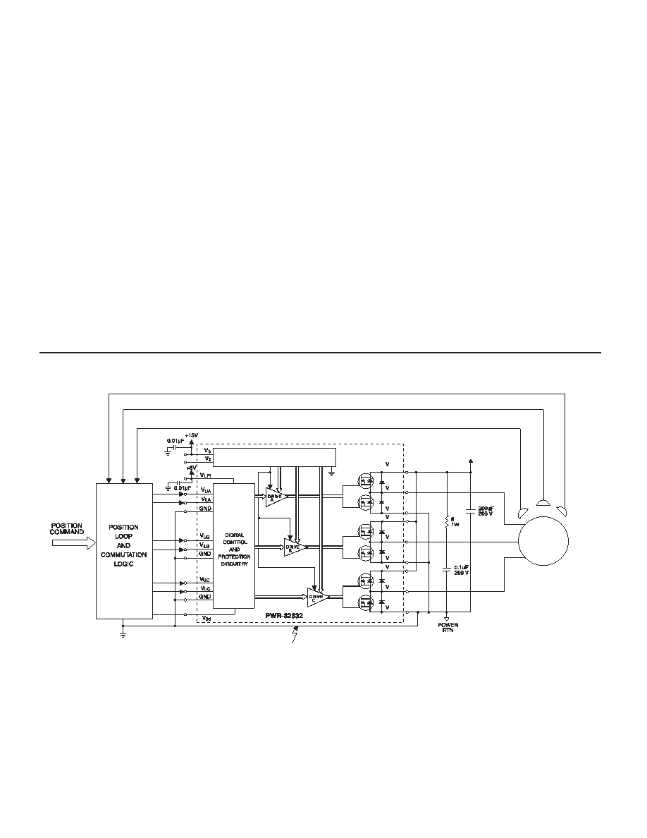
The commutation/control circuitry can be as simple as discrete
logic with PWM, or as sophisticated as a microprocessor or cus-
tom ASIC, depending on the system requirements. The Block
diagram in FIGURE 4 shows a typical interface of the PWR-
82332 with a motor and commutation logic in a Servo-Amp
System.
SHUT-DOWN INPUT (Vsd)
Pin 23 (Vsd) provides a digital shut-down input, which allows the
user to completely turn off both the upper and lower output tran-
sistors in all 3 phases. Application of a logic ‘1’ to the Vsd input
will disable the Digital/Control Protection circuitry thereby turning
off all output transistors. The circuitry remains disabled and will
POWER SUPPLY/BIAS GENERATION
HALL
EFFECT
DEVICE
V
CC A
CC C
O C
SS C
O A
SS A
CC
MOTOR
CC B
O B
SS B
+
FIGURE 4. PWR-82332 TYPICAL INTERFACE WITH A MOTOR
not respond to signals on the VL or VU inputs while the Vsd has
a logic ‘1’ applied. See FIGURE 5. When the user or the sense
circuitry ( as in FIGURE 6) returns the Vsd input to a logic ‘0’, the
output transistors will respond to the corresponding digital input.
This feature can be used with the external current limit or tem-
perature sense circuitry to disable the drive if a fault condition
occurs (see FIGURE 6).
INTERNAL PROTECTION CIRCUITRY
The hybrid contains digital protection circuitry, which prevents in-
line transistors from conducting simultaneously. This, in effect,
would short circuit the power supply and would damage the out-
put stage of the hybrid. The circuitry allows only proper input sig-
nal patterns to cause output conduction. TABLE 3. shows these
timing relationships.
If an improper input requested that the
upper and lower transistors of the same phase conduct together,
the output would be a high impedance until removal of the illegal
code from the input of the PWR-82332. A dead time is not
required for the signals at the VU and VL pins.
CRITICAL GROUND PATH
To prevent damage to the internal drive circuitry, the differential voltage between
GND (pins 19,22,26) and Vss (pins 1, 5, 8) must not exceed ± 3V max, dc or peak
相关PDF资料 |
PDF描述 |
|---|---|
| PWR-82333-330 | BRUSHLESS DC MOTOR CONTROLLER, DFM26 |
| PWR-82331-310 | BRUSHLESS DC MOTOR CONTROLLER, DFM26 |
| PWR-82333-310 | BRUSHLESS DC MOTOR CONTROLLER, DFM26 |
| PWR-82340-320 | BRUSHLESS DC MOTOR CONTROLLER, 50 A, UFM18 |
| PWR-82340-300 | BRUSHLESS DC MOTOR CONTROLLER, 50 A, UFM18 |
相关代理商/技术参数 |
参数描述 |
|---|---|
| PWR-82332-300 | 制造商:未知厂家 制造商全称:未知厂家 功能描述:DC Motor Controller/Driver |
| PWR-82332-310 | 制造商:未知厂家 制造商全称:未知厂家 功能描述:Industrial Control IC |
| PWR-82332-320 | 制造商:未知厂家 制造商全称:未知厂家 功能描述:Industrial Control IC |
| PWR-82333 | 制造商:未知厂家 制造商全称:未知厂家 功能描述:Drives (Power Amplifiers)|3-Phase Bridge. Class K Hybrid. NASA Drawing #SSQ22691 |
| PWR-82333-100 | 制造商:未知厂家 制造商全称:未知厂家 功能描述:DC Motor Controller/Driver |
发布紧急采购,3分钟左右您将得到回复。