- 您现在的位置:买卖IC网 > PDF目录98066 > PWR-82520-400 (DATA DEVICE CORP) BRUSHLESS DC MOTOR CONTROLLER, 15 A, DIP41 PDF资料下载
参数资料
| 型号: | PWR-82520-400 |
| 厂商: | DATA DEVICE CORP |
| 元件分类: | 运动控制电子 |
| 英文描述: | BRUSHLESS DC MOTOR CONTROLLER, 15 A, DIP41 |
| 封装: | DIP-41 |
| 文件页数: | 7/12页 |
| 文件大小: | 174K |
| 代理商: | PWR-82520-400 |
4
VBUS
PHASE A
UPPER
PHASE A
LOWER
PHASE B
UPPER
PHASE B
LOWER
Rsense
PHASE A
PHASE B
PHASE C
-
+
OFF
ON
I
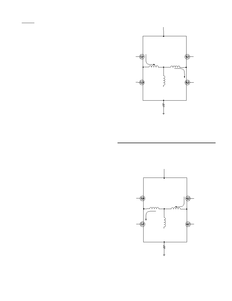
FIGURE 2A. COMPLEMENTARY FOUR-QUANDRANT
DRIVE FIRST HALF OF PWM CYCLE
VBUS
PHASE A
UPPER
PHASE A
LOWER
PHASE B
UPPER
PHASE B
LOWER
Rsense
PHASE A
PHASE B
PHASE C
+
_
ON
OFF
I
FIGURE 2B. COMPLEMENTARY FOUR-QUADRANT DRIVE
SECOND HALF OF PWM CYCLE
The ENABLE input signal provides quick start and shutdown of
the output power switches. In addition, built-in power sequence
fault protection turns off the output in case of low power supply
voltages.
The hybrid features dual current limiting functions. The input
command amplifier output is limited to 10.8V thus limiting the
current under normal operation. In addition, there is a built in
over current limit which trips at 14 Amps, protecting the hybrid as
well as the load.
BASIC OPERATION
The PW-82520 utilizes a complimentary four-quadrant drive
technique to control current in the load.
The complimentary
drive has the following advantages over the standard drive:
1. Maximum holding torque and position accuracy
2. Linear current control through zero
3. No deadband at zero
The complementary drive design uses a 50% PWM duty cycle
for a zero command signal. For a zero input command, a pair of
MOSFETs are turned on in the drive, Phase A upper & Phase B
lower as shown in FIGURE 2A, to supply current into the load for
the first half of the PWM cycle. This is the same mode of oper-
ation for the standard four-quadrant drive as shown in FIGURE
3A/B. During the second half of the PWM cycle, a second pair
of transistors are turned on, Phase A lower & Phase B upper as
shown in FIGURE 2B, for the flyback current and to provide load
current in the opposite direction.
This is normally the dead time for standard four-quadrant drive
as shown in FIGURE 3B. The result is current flowing in both
directions in the motor for each PWM cycle. The advantage this
has over standard four-quadrant drive is that at 50% duty cycle,
which corresponds to zero average current in the motor, holding
torque is provided. The motor current at 50% duty cycle is sim-
ply the magnetizing current of the motor winding.
Using the complimentary four-quadrant technique allows the
motor direction to be defined by the duty cycle. Relative to a
given switch pair i.e., Phase A upper and Phase B lower, a duty
cycle greater than 50% will result in a clockwise rotation where-
as a duty cycle less than 50% will result in a counter clockwise
rotation. Therefore, with the use of average current mode con-
trol, direction can be controlled without the use of a direction bit
and the current can be controlled through zero in a very precise
and linear fashion.
The PW-82520 contains all the circuitry required to close an
average current mode control loop around a complimentary four-
quadrant drive. The PWR-82520 use of average current mode
control simplifies the control loop by eliminating the need for
slope compensation and eliminating the pole created by the
motor inductance. These two effects are normally associated
with 50% duty cycle limitations when implementing standard
peak current mode control.
相关PDF资料 |
PDF描述 |
|---|---|
| PWR-SMP211BNI | 8 A SWITCHING CONTROLLER, 272 kHz SWITCHING FREQ-MAX, PDIP16 |
| PWR-SMP211SRI | SWITCHING CONTROLLER, PDSO16 |
| S-3510ACFJA | 0 TIMER(S), REAL TIME CLOCK, PDSO8 |
| S-3510ADFJ | REAL TIME CLOCK, PDSO8 |
| S-3510AFFJ | REAL TIME CLOCK, PDSO8 |
相关代理商/技术参数 |
参数描述 |
|---|---|
| PWR-82520N10-100 | 制造商:未知厂家 制造商全称:未知厂家 功能描述:Industrial Control IC |
| PWR-82520N10-110 | 制造商:未知厂家 制造商全称:未知厂家 功能描述:Industrial Control IC |
| PWR-82520N10-120 | 制造商:未知厂家 制造商全称:未知厂家 功能描述:Industrial Control IC |
| PWR-82520N10-300 | 制造商:未知厂家 制造商全称:未知厂家 功能描述:Industrial Control IC |
| PWR-82520N10-310 | 制造商:未知厂家 制造商全称:未知厂家 功能描述:Industrial Control IC |
发布紧急采购,3分钟左右您将得到回复。