- 您现在的位置:买卖IC网 > PDF目录296887 > Q8015L5TP 800 V, 15 A, TRIAC, TO-220AB PDF资料下载
参数资料
| 型号: | Q8015L5TP |
| 元件分类: | 晶闸管 |
| 英文描述: | 800 V, 15 A, TRIAC, TO-220AB |
| 封装: | ISOLATED TO-220AB, 3 PIN |
| 文件页数: | 9/10页 |
| 文件大小: | 283K |
| 代理商: | Q8015L5TP |
Triacs
Data Sheets
http://www.littelfuse.com
E2 - 8
2004 Littelfuse, Inc.
+1 972-580-7777
Thyristor Product Catalog
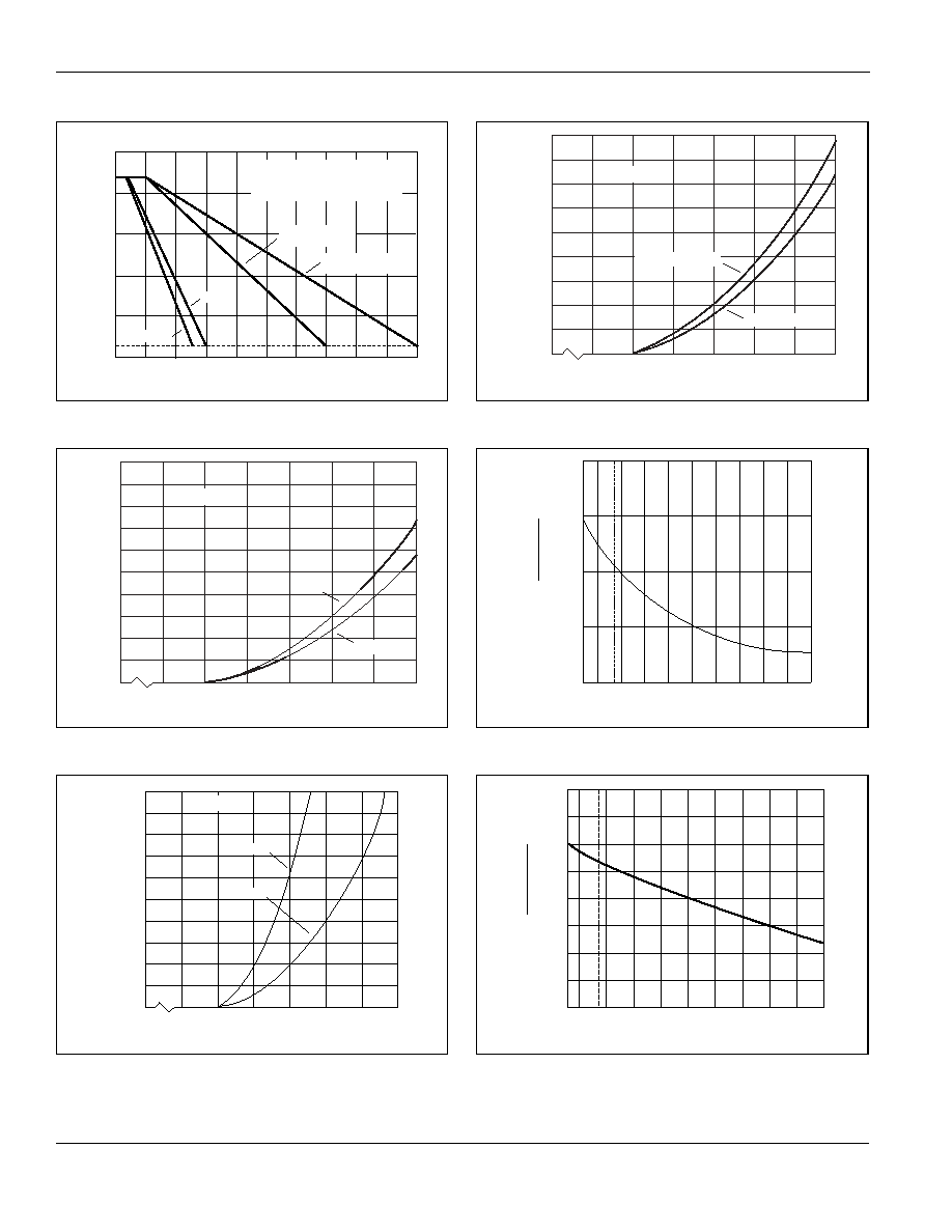
Figure E2.7 Maximum Allowable Ambient Temperature versus
On-state Current
Figure E2.8 On-state Current versus On-state Voltage (Typical)
(0.8 A and 1 A)
Figure E2.9 On-state Current versus On-state Voltage (Typical)
(4 A, 6 A, 8 A, and 10 A)
Figure E2.10 On-state Current versus On-state Voltage (Typical)
(15 A and 25 A)
Figure E2.11 Normalized DC Gate Trigger Current for All Quadrants
versus Case Temperature
Figure E2.12 Normalized DC Gate Trigger Voltage for All Quadrants
versus Case Temperature
120
100
80
60
40
25
20
0
0.2
0.4
0.6
0.8
1.0
1.2
1.4
1.6
1.8
2.0
TO-220 Devices and
TO-202 (Type 1 and 3)
RMS On-state Current [IT (RMS)] — Amps
Maximum
Allowable
Ambient
Temperature
(T
A
)—
C
1 A TO-92
0.8 A TO-92
CURRENT WAVEFORM: Sinusoidal
LOAD: Resistive or Inductive
CONDUCTION ANGLE: 360
FREE AIR RATING – NO HEATSINK
TO-202 (TYPE 2 and 4)
TO-251
0
0.6
0.8
1.0
1.2
1.4
1.6
1.8
0
1
2
3
4
5
6
7
8
9
10
Positive or Negative Instantaneous On-state Voltage (v
T) – Volts
Positive
or
Negative
Instantaneous
On-state
Current
(i
T
)–
Amps
T
C = 25 C
1 A
0.8 A
0
0.6
0.8
1.0
1.2
1.4
1.6
1.8
0
2
4
6
8
10
12
14
16
18
20
Positive or Negative Instantaneous On-state Voltage (v
T) – Volts
Positive
or
Negative
Instantaneous
On-state
Current
(i
T
)–
Amps
T
C = 25 C
6-10 A
4A
0
0.6
0.8
1.0
1.2
1.4
1.6
1.8
0
10
20
30
40
50
60
70
80
90
Positive or Negative Instantaneous On-state Voltage (v
T) – Volts
Positive
or
Negative
Instantaneous
On-state
Current
(i
T
)–
Amps
T
C = 25 C
15 A and 25 A
25 A and 35 A Fastpak
-65
-40
-15
+25
+65
+125
1.0
2.0
3.0
4.0
Case Temperature (T
C) – C
Ratio
of
I GT
(T
C
=
25
C)
-65
-15
-40
+25
+65
+125
0
.5
1.0
1.5
2.0
Case Temperature (TC) – C
Ratio
of
V
GT
V
GT
(T
C
=
25
C)
相关PDF资料 |
PDF描述 |
|---|---|
| Q8015N5RP | 800 V, 15 A, TRIAC, TO-263AB |
| Q8015N5TP | 800 V, 15 A, TRIAC, TO-263AB |
| Q8015R5TP | 800 V, 15 A, TRIAC, TO-220AB |
| Q2006LTTPV | 200 V, 6 A, TRIAC WITH INT TRIGGER, TO-220AB |
| Q2006LTTP | 200 V, 6 A, TRIAC WITH INT TRIGGER, TO-220AB |
相关代理商/技术参数 |
参数描述 |
|---|---|
| Q8015L5V | 制造商:未知厂家 制造商全称:未知厂家 功能描述:TRIAC|800V V(DRM)|15A I(T)RMS|TO-220AB |
| Q8015L6 | 制造商:TECCOR 制造商全称:TECCOR 功能描述:Alternistor Triacs |
| Q8015L6V | 制造商:未知厂家 制造商全称:未知厂家 功能描述:TRIAC|800V V(DRM)|15A I(T)RMS|TO-220AB |
| Q8015L9 | 制造商:未知厂家 制造商全称:未知厂家 功能描述:TRIAC|800V V(DRM)|15A I(T)RMS|TO-220 |
| Q8015N5 | 制造商:LITTELFUSE 制造商全称:Littelfuse 功能描述:Triacs (0.8 A to 35 A) |
发布紧急采购,3分钟左右您将得到回复。