- 您现在的位置:买卖IC网 > Datasheet目录46 > QPI-8LZ-01 (Vicor Corporation)IC HOT SWAP EMI FILTER 16LGA Datasheet资料下载
参数资料
| 型号: | QPI-8LZ-01 |
| 厂商: | Vicor Corporation |
| 文件页数: | 16/17页 |
| 文件大小: | 1498K |
| 描述: | IC HOT SWAP EMI FILTER 16LGA |
| 标准包装: | 20 |
| 系列: | Picor®, QUIETPOWER® |
| 类型: | 热交换开关 |
| 应用: | AdvancedTCA |
| 内部开关: | 是 |
| 电流限制: | 6A |
| 电源电压: | 36 V ~ 76 V |
| 工作温度: | -40°C ~ 125°C |
| 安装类型: | 表面贴装 |
| 封装/外壳: | * |
| 供应商设备封装: | * |
| 包装: | 管件 |
| 其它名称: | 1102-1092-5 |
C
E
Picor Corporation ?picorpower.com
QPI-8
Rev 1.5, Page 16 of 17
QPI-8
QUIETPOWER
?/DIV>
QPI-8 PCB Layout Recommendations:
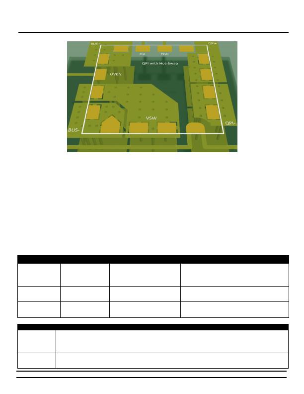
Figure 31 - 3D view of paralleling planes underneath the QPI-8.
PCB Layout
When laying out the QPI-8 EMI filter it is important for the
designer to be aware of the radiated EMI field that all
converters emit and to place the QPI-8 outside of this field
area. It is also recommended that the bus lines feeding into
the QPI filter are not routed such that they lie between the
QPI and the converter, or that their copper planes over-lap on
inner layers. This can cause EMI noise to be coupled from
input to output via the parasitic capacitance between the
planes. In Figure 31, the QPI-8 is located ~1.5 inches from the
converters input pins to keep the radiated EMI from by-
passing the filter and coupling directly to the BUS feeds.
Post Solder Cleaning
Picors LZ version QP SIPs are not hermetically sealed and
must not be exposed to liquid, including but not limited to
cleaning solvents, aqueous washing solutions or pressurized
sprays. When soldering, it is recommended that no-clean flux
solder be used, as this will ensure that potentially corrosive
mobile ions will not remain on, around, or under the module
following the soldering process. For applications where the
end product must be cleaned in a liquid solvent, Picor
recommends using the QPI-8LZ-01, open-frame version of the
EMI filter.
QPI-8 Mechanical Data
Datum
Units
QPI-8LZ
QPI-8LZ-01
Notes
FITS
Failure/Billion Hrs.
330
330
FITS based on the BellCore Standard TR-332
MTBF
Million Hrs.
3
3
MTBFs based on the BellCore Standard TR-332
Weight
grams
4.7
3.4
MSL
3
3
Peak reflow
Temperature
癈/20 seconds
245
245
IPC/JEDEC J-STD-020D
- E
B
Part #
Description:
QPI-8-EVAL1
A QPI-8LZ mounted on a small evaluation board with screw terminal blocks to allow for easy connection into an
existing system.
QPI-8-CB1
A QPI-8LZ mounted on a carrier board designed for use with DOSA compliant footprint dc-dc converters. Screw
terminal blocks to allow for easy connection into an existing system.
相关PDF资料 |
PDF描述 |
|---|---|
| SA56004HD,118 | IC TEMP SENSOR DIGITAL 8SOIC |
| SC2463TSTRT | IC REG QD BCK/LINEAR 28TSSOP |
| SC338AIMSTRT | IC REG CTRLR DUAL POS ADJ 10MSOP |
| SC402BMLTRT | IC REG DL BCK/LINEAR SYNC 32MLPQ |
| SC403MLTRT | IC REG DL BCK/LINEAR SYNC 32MLPQ |
相关代理商/技术参数 |
参数描述 |
|---|---|
| QPI-9 | 制造商:VICOR 制造商全称:Vicor Corporation 功能描述:Hot-Swap SiP With VI Chip EMI Filter |
| QPI-9-CB1 | 制造商:Vicor Corporation 功能描述:QPI-9LZ Filter w/ Hot-Swap Carrier Board for 24 V VI Chip "-CB" Boards up to 6A |
| QPI-9L | 制造商:VICOR 制造商全称:Vicor Corporation 功能描述:VI Chip Input EMI Filters |
| QPI-9LZ | 制造商:VICOR 制造商全称:Vicor Corporation 功能描述:Hot-Swap SiP With VI Chip EMI Filter |
| QPI-9LZ-01 | 制造商:VICOR 制造商全称:Vicor Corporation 功能描述:Hot-Swap SiP With VI Chip EMI Filter |
发布紧急采购,3分钟左右您将得到回复。