- 您现在的位置:买卖IC网 > PDF目录299801 > QPO-1Q (Vicor Corporation) Output Ripple Attenuation SiP PDF资料下载
参数资料
| 型号: | QPO-1Q |
| 厂商: | Vicor Corporation |
| 元件分类: | DC/DC变换器 |
| 英文描述: | Output Ripple Attenuation SiP |
| 中文描述: | 输出纹波衰减的SiP |
| 文件页数: | 5/8页 |
| 文件大小: | 144K |
| 代理商: | QPO-1Q |
Set your site on PICOR at www.picorpower.com
PRELIMINARY
Vicor Corp. Tel: 800-735-6200, 978-470-2900 Fax: 978-475-6715
QPO-1 Data Sheet
Page 5 of 8
The slope adjust feature can be set to zero providing relative
constant headroom versus load using an RSA of 100k. The user
can optimize performance based on the expected variation in load
current and the desired power dissipation range. The formula
below should be used to calculate the RSA value for the desired
headroom versus current slope. If the peak detector is enabled,
the peak of the ripple will be added back to the headroom at a
given load condition.
RSA = ((I*0.05)/V) *2500
Example: For a 5A maximum load and a 150mV
reduction in headroom.
RSA =((5A*0.05/0.15V)*2500 = 4.167k
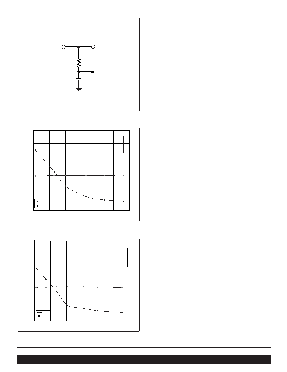
Peak Detector Function
This feature dynamically adds to the headroom voltage to
accommodate converter ripple variation. This feature can be
enabled by connecting the PEAKIN pin to the QPOIN pin and
disabled by putting a small RC filter at the PEAKIN pin as shown
in Figure 8.
The active loop performance has been optimized for 45 degrees
of phase margin over the expected load range. CCO shown in Figs
1 and 2 must be a low ESR ceramic capacitor. Loading the
QPO-1 directly with low ESR ceramic capacitance will affect the
phase margin and is not recommended. The distributed load
capacitance and inductance of the load path will vary depending
on the application. The effects of a distributed load impedance
on phase margin when very low ESR load capacitance is present
will typically be mitigated by the distributed inductance of the
load path. The transient load response in Figure 4 was measured
with approximately 10nH of distributed inductance between
QPO-1 output and the load board which had a 15F low ESR
ceramic capacitor across the static load resistance.
The following is a summary of the optional configurations that a
user can select for the QPO-1.
No slope adjust, no peak detect:
fixed headroom over ripple amplitude and current.
Same as above, but with peak detect enabled:
peak of ripple amplitude is added to the headroom voltage
optimizing headroom with varying ripple amplitude.
No peak detection with slope adjust:
to improve transient load range and efficiency trading off
attenuation at high current.
Using both peak detection and slope adjust:
to accommodate ripple amplitude variation with increased
transient capability and efficiency.
Module
+ OUT
QPOIN
PEAKIN
1k
0.1
F
Figure 8 – Peak detector Disable Circuit
QPO-1 Attenuation vs. Power
Iload=10A
1% Rhr std. values for VOUT=3.3V 15V 28V
Rss=100k (delta Vhr = 0mV from 0.1 to 10A)
3.3V
15V
28V
69.8k 324k 602k
47.5k 215k 402k
39.2k 178k 332k
30.1k 137k 255k
24.9k 113k 210k
21k 95.3k 178k
-60
-50
-40
-30
-20
-10
0
1234
Watts
dB
500kHz
50Hz
Figure 9 – Power vs Attenuation without slope
QPO-1 Attenuation vs. Power
Iload=10A
1% Rhr std. values for VOUT=3.3V 15V 28V
Rss=7.1k (delta Vhr =150mV from 0.1 to 10A)
14.3k 64.9k 121k
16.5k 75k 140k
18.2k 82.5k 154k
21k 95.3k 178k
22.6k 102k 191k
24.9k 113k 210k
3.3V 15V 28V
27.4k 124k 232k
-60
-50
-40
-30
-20
-10
0
12
34
Watt
dB
500kHz
50Hz
Figure 10 – Power vs Attenuation with slope adjust
相关PDF资料 |
PDF描述 |
|---|---|
| QPO-2EVAL1 | Evaluation Board for QPO-2 Active Output Filter |
| QPO-2L | QPO-2L Low Voltage Output Ripple Attenuator |
| QS54FCT2240ATZB | FCT SERIES, DUAL 4-BIT DRIVER, INVERTED OUTPUT, PZIP20 |
| QS54FCT2240TZB | FCT SERIES, DUAL 4-BIT DRIVER, INVERTED OUTPUT, PZIP20 |
| QS74FCT2244CTZ | FCT SERIES, DUAL 4-BIT DRIVER, TRUE OUTPUT, PZIP20 |
相关代理商/技术参数 |
参数描述 |
|---|---|
| QPO-2EVAL1 | 制造商:VICOR 制造商全称:Vicor Corporation 功能描述:Evaluation Board for QPO-2 Active Output Filter |
| QPO-2-EVAL1 | 功能描述:EVALUATION BOARD FOR QPO-2 RoHS:是 类别:编程器,开发系统 >> 评估演示板和套件 系列:Picor®, QUIETPOWER® 标准包装:1 系列:PSoC® 主要目的:电源管理,热管理 嵌入式:- 已用 IC / 零件:- 主要属性:- 次要属性:- 已供物品:板,CD,电源 |
| QPO-2L | 制造商:POWERBOX 制造商全称:Powerbox 功能描述:OUTPUT RIPPLE ATTENUATOR |
| QPO-2LZ | 功能描述:0.3-5.5V 20A OUT RIP ATTENUATOR RoHS:是 类别:集成电路 (IC) >> 接口 - 滤波器 - 有源 系列:Picor®, QUIETPOWER® 产品培训模块:Lead (SnPb) Finish for COTS Obsolescence Mitigation Program 标准包装:1,000 系列:- 滤波器类型:连续时间,带通低通 频率 - 截止或中心:150kHz 滤波器数:4 滤波器阶数:8th 电源电压:4.74 V ~ 11 V,±2.37 V ~ 5.5 V 安装类型:表面贴装 封装/外壳:28-SOIC(0.295",7.50mm 宽) 供应商设备封装:28-SOIC W 包装:带卷 (TR) |
| QPO-2LZ-01 | 功能描述:IC INTERFACE FILTER RoHS:是 类别:集成电路 (IC) >> 接口 - 滤波器 - 有源 系列:Picor®, QUIETPOWER® 产品培训模块:Lead (SnPb) Finish for COTS Obsolescence Mitigation Program 标准包装:1,000 系列:- 滤波器类型:连续时间,带通低通 频率 - 截止或中心:150kHz 滤波器数:4 滤波器阶数:8th 电源电压:4.74 V ~ 11 V,±2.37 V ~ 5.5 V 安装类型:表面贴装 封装/外壳:28-SOIC(0.295",7.50mm 宽) 供应商设备封装:28-SOIC W 包装:带卷 (TR) |
发布紧急采购,3分钟左右您将得到回复。