- 您现在的位置:买卖IC网 > PDF目录224961 > QT114-D IC-QPROX SENSOR PDF资料下载
参数资料
| 型号: | QT114-D |
| 英文描述: | IC-QPROX SENSOR |
| 中文描述: | 集成电路量研传感器 |
| 文件页数: | 6/12页 |
| 文件大小: | 310K |
| 代理商: | QT114-D |

for example due to changes in Cs or Cx over the operating
temperature range.
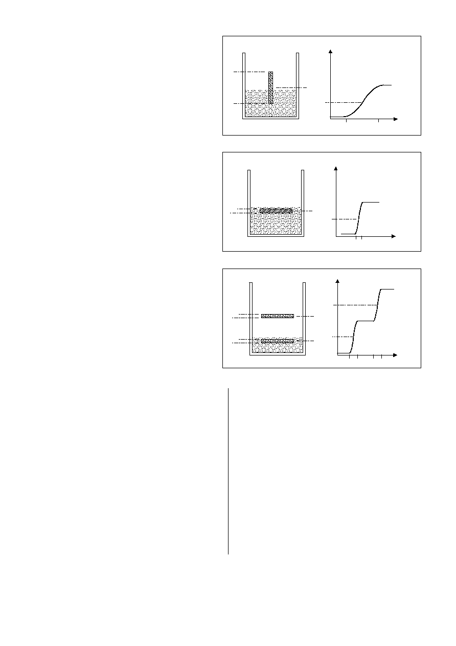
Figure 2-2 shows the response from a horizontal strip of
the same surface area; the signal exhibits a very rapid rise
in signal between points l1 and l2. Variations in circuit
gain or signal drift have much less of an effect on the trip
point with this orientation.
In some cases (thin walled vessels for example) it may be
sufficient to have a small round or square electrode patch
on the exterior.
Figure 2-3 shows the response from a twin-level external
electrode set. The use of two horizontal electrode planes
or tiers creates well-defined trip points that can be used to
sense both 'low' and 'high' levels. A crossing of threshold
T1 will be reflected in the OUT1 signal, while T2 will be
reflected on OUT2.
2.1 EXTERNAL ELECTRODES
External electrodes should be electrically conductive;
metal foils and conductive carbon are both possible. Care
should be taken that other objects or people near the
vessel will not touch the electrode; in some cases
shielding around the electrode with grounded metal will be
required to prevent disturbances. If used, the shield
element should be spaced apart from the electrode by an
air gap or a low-density foam to reduce Cx loading.
The required surface area of the external electrode will
depend on the amount of signal needed to bracket the
detection threshold, which in turn will depend in part on Cs
and stray Cx. External electrodes sensing through thick
walls and/or sensing low permittivity fluids will require
larger surface areas than those sensing water through thin
plastic, for example. External electrodes are more likely to
require potentiometer trimming to achieve reliable
operation (Figure 1-1, also Section 3.2).
Note that external electrodes used with conductive
solutions (i.e. aqueous liquids) do not measure the
permittivity of the fluid: they actually measure the
permittivity of the vessel wall, between 2 plates: the
electrode (plate 1) and the fluid (plate 2, effectively a
variable-area ground plate): if the fluid were to be replaced
with mercury the signal would be unchanged. A 20%
thickness variation in the vessel wall will therefore
introduce about a 20% variation in the resulting
capacitance; if the vessel wall cannot be controlled
accurately enough in production, serious sensing errors may
occur.
When external electrodes are used to sense non-aqueous
substances (like oils or gasoline), the vessel wall dielectric
becomes a lessor contributor to the overall signal, which is
then heavily dominated by the permittivity of the fluid. The
lower the permittivity of the fluid the greater its dominance.
2.2 INTERNAL PROBES
When used with aqueous fluids or other electrically
conducting liquids, internal probes should be insulated with a
plastic layer. See also Section 2.1 for a discussion of
electrodes when used with conductive fluids. Aqueous
probes should be 100% insulated, even on the cut end of a
wire probe. The slightest pinhole of exposed metal anywhere
on an immersed part of the probe will immediately convert
the probe into a bare-metal probe (see Section 2.2.5).
Numerous types of internal point-level probes are possible.
2.2.1 DISC PROBES
The simplest internal geometry is probably a disc probe
(Figure 2-4), having at least one planar surface ('tier')
parallel to the fluid surface. The sensing error can be
minimized by making the tier thin, so that the signal
transitions abruptly higher (see Figure 2-2) as the fluid
covers the tier.
A notable difficulty with disc probes is the task of insulating
them with a uniform, repeatable thickness of insulation.
2.2.2 SPIRAL WIRE PROBES
A spiral solid-wire probe is simple to construct (Figure 2-5),
and has the advantage of being pre-insulated in a wide
choice of plastics from inexpensive PVC to PTFE. These
probe types provide a large step-function of capacitance
localized at the desired trip point, and are easy to form.
Spiral wire probes are most effective in water-based fluids;
they are not as effective in oils and other nonconductive
substances.
- 3 -
Figure 2-1 Signal vs. Level for an External Vertical Strip
Figure 2-2 Signal vs. Level for an External Horizontal Strip
Figure 2-3 Signal vs. Level for Twin Horizontal Strips
Signal
Level
l
1
l
2
T
1
T
1
l
1
l
2
l
3
l
4
T
2
l
3
l
4
T
2
S ignal
Level
l
1 l2
T
1
l
2
l
1
T
1
Signal
Level
l
1
l
2
T
1
l
1
l
2
T
1
相关PDF资料 |
PDF描述 |
|---|---|
| QT114-S | IC-SMD-QPROX SENSOR |
| QT12C-SERIES | Peripheral IC |
| QT12E-SERIES | Peripheral IC |
| QT12HC-SERIES | Peripheral IC |
| QT12T-SERIES | Peripheral IC |
相关代理商/技术参数 |
参数描述 |
|---|---|
| QT114-DG | 制造商:Quantum Corp 功能描述:IC QPROX SENSOR DIP8 114 |
| QT114-IS | 制造商:Quantum Corp 功能描述:IC QPROX SENSOR SMD SOIC8 114 |
| QT114-ISG | 功能描述:板机接口移动感应器和位置传感器 INTEGRATED-CIRCUIT RoHS:否 制造商:Panasonic Electric Works 封装 / 箱体:TO-5 感应距离:3 m 输出类型:Digital 电源电压-最大:6 V 电源电压-最小:2.3 V 电源电流: 最大工作温度:+ 60 C 封装:Bulk |
| QT114R-SG | 功能描述:板机接口移动感应器和位置传感器 INTEGRATED-CIRCUIT RoHS:否 制造商:Panasonic Electric Works 封装 / 箱体:TO-5 感应距离:3 m 输出类型:Digital 电源电压-最大:6 V 电源电压-最小:2.3 V 电源电流: 最大工作温度:+ 60 C 封装:Bulk |
| QT114-S | 制造商:未知厂家 制造商全称:未知厂家 功能描述:IC-SMD-QPROX SENSOR |
发布紧急采购,3分钟左右您将得到回复。