参数资料
| 型号: | QT60248C-ASG |
| 厂商: | Atmel |
| 文件页数: | 2/28页 |
| 文件大小: | 0K |
| 描述: | IC TOUCH SENSOR 24KEY 32TQFP |
| 标准包装: | 250 |
| 系列: | QMatrix™, QProx™ |
| 类型: | 电容性 |
| 输入数/键: | 24 键 |
| 分辨率(位): | 9,11 b |
| 评估套件: | 可供 |
| 数据接口: | 串行,SPI? |
| 电源电压: | 3 V ~ 5 V |
| 电流 - 电源: | 25mA |
| 工作温度: | -40°C ~ 105°C |
| 安装类型: | 表面贴装 |
| 封装/外壳: | 32-TQFP |
| 供应商设备封装: | 32-TQFP(7x7) |
| 包装: | 托盘 |
| 配用: | 427-1087-ND - BOARD EVAL QT60248-AS QMATRIX |
第1页当前第2页第3页第4页第5页第6页第7页第8页第9页第10页第11页第12页第13页第14页第15页第16页第17页第18页第19页第20页第21页第22页第23页第24页第25页第26页第27页第28页
3 Serial Communications
These devices use SPI communications, in slave mode.
The host device always initiates communications sequences;
the QT is incapable of chattering data back to the host. This is
intentional for FMEA purposes so that the host always has total
control over the communications with the QT60xx8. In SPI
mode the device is a slave, so that even return data following a
command is controlled by the host.
A command from the host always ends in a response of some
kind from the QT. Some transmission types from the host or the
QT employ a CRC check byte to provide for robust
communications.
A DRDY line is provided that handshakes transmissions.
Generally this is needed by the host from the QT to ensure that
transmissions are not sent when the QT is busy or has not yet
processed a prior command.
Initiating or Resetting Communications: After a reset, or,
should communications be lost due to noise or out-of-sequence
reception, the host should send a 0x0f (return last command)
command repeatedly until the compliment of 0x0f, i.e. 0xf0, is
received back. Then, the host can resume normal run mode
communications from a clean start.
Poll rate: The typical poll rate in normal ‘run’ operation should
be no faster than once per 10ms; 25ms is more than fast
enough to extract status data using the 0x06 command (report
first key: see page 13) in most situations. Streaming multi-byte
response commands like the 0x0d command (dump setups: see
page 13) or multi-byte response commands like 0x07 can and
should pace at the maximum possible rate.
Run Poll Sequence: In normal run mode the host should limit
traffic with a minimalist control structure (see also Section 4.18).
The host should just send a 0x06 command until something
requires a deeper state inspection. If there is more than one key
in detect, the host should use 0x07 to find which additional keys
are in detect. If there is an error, the host should ascertain the
error type based on commands 0x0b and 0x0c and take
appropriate action. Issuing a 0x07 command all the time is
wasteful of bandwidth, requires more host processor time, and
actually conveys less information (no error flags are sent via a
0x07 command).
3.1 DRDY Pin
DRDY is an open-drain output with an internal 20K ~ 50K pullup
resistor.
Serial communications pacing is controlled by this pin. The host
is permitted to send data only when DRDY is high. After a byte
is received DRDY will always go low even if only for a few
microseconds; during this period the host should not send data.
Therefore, after each byte transmission the host should first
check that DRDY is high again.
If the host desires to send a byte to the QT it should behave as
follows:
1. If DRDY is low, wait
2. If DRDY is high: send a command to QT
3. Wait at least 40s (time S5 in Figure 3-3: DRDY is
guaranteed to go low before this 40s expires)
4. Wait until DRDY is high (it may already be high again)
5. Send next command or a null byte 0x00 to QT
The time it takes for DRDY to go high again after a command
depends on the command. Following is a list of commands and
the time required to process them and then raise DRDY:
0x0E Eeprom CRC
[ 25ms
0x01 Load Setups
[ 25ms
All other commands:
[ 2ms between bytes;
[ 40s after CRC byte is sent
Other DRDY specs:
Min time DRDY is low: 1s
Min time DRDY is low
after reset:
1ms
3.2 SPI Communications
SPI communications operates in slave mode only, and obeys
DRDY control signaling. The clocking is as follows:
Clock idle:
High
Clock shift out edge:
Falling
Clock data in edge:
Rising
Max clock rate:
1.5MHz
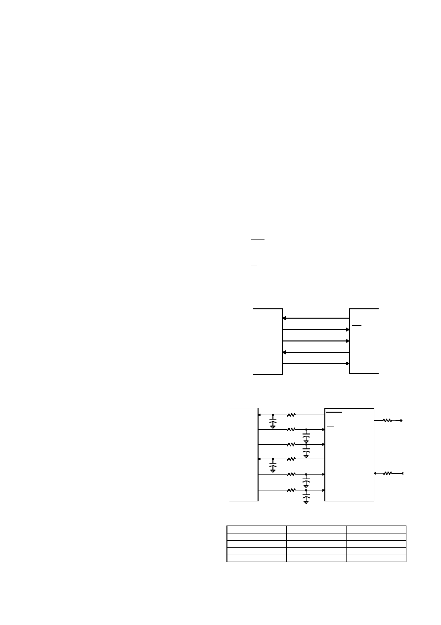
SPI mode requires 5 signals to operate:
MOSI - Master out / Slave in data pin; used as an input for
data from the host (master). This pin should be connected
to the MOSI (DO) pin of the host device.
MISO - Master in / Slave out data pin; used as an output for
data to the host. This pin should be connected to the MISO
lQ
10
QT60248-AS R4.02/0405
Figure 3-2 Filtered SPI Connections
MOSI
MISO
SCK
DRDY
SS
QT60xx8 Circuit
Ra
1K
Ra
RESET
1K
Host MCU
1K
Yn
Xn
X drives
(1 of 8
shown)
Y Lines
(1 of 3
shown)
Ca
1nF
SCK
MISO
MOSI
P_IN
P_OUT1
P_OUT2
1nF
2,200
50kHz
470pF
2,200
100kHz
270pF
1,000
400kHz
100pF
680
1.5MHz
Ca
Ra
SPI Clock Rate
Recommended Values of Ra & Ca
Figure 3-1 Basic SPI Connections
MOSI
MISO
SCK
DRDY
P_OUT
P_IN
SS
Host MCU
QT60xx8
相关PDF资料 |
PDF描述 |
|---|---|
| SA571N | IC COMPANDOR DUAL GAIN 16-DIP |
| SA572N | IC COMPANDOR 2CHAN GAIN 16-DIP |
| SA575NG | IC COMPANDOR 2CHAN GAIN 20-DIP |
| SI4113-D-ZT1 | IC SYNTHESIZER RF1/RF2 24TSSOP |
| SI51210-A01AFM | IC CLK GEN FACTORY CONFIG 6TDFN |
相关代理商/技术参数 |
参数描述 |
|---|---|
| QT60248C-ASG-SL683 | 功能描述:接口 - 专用 Integrated Circuit RoHS:否 制造商:Texas Instruments 产品类型:1080p60 Image Sensor Receiver 工作电源电压:1.8 V 电源电流:89 mA 最大功率耗散: 最大工作温度:+ 85 C 安装风格:SMD/SMT 封装 / 箱体:BGA-59 |
| QT60320 | 制造商:未知厂家 制造商全称:未知厂家 功能描述:32 KEY QMATRIX CHARGE TRANSFER IC |
| QT60320-AS | 制造商:未知厂家 制造商全称:未知厂家 功能描述:32 KEY QMATRIX CHARGE TRANSFER IC |
| QT60320C | 制造商:QUANTUM 制造商全称:QUANTUM 功能描述:32-KEY QMATRIX CHARGE-TRANSFER IC |
| QT60320C-A | 制造商:QUANTUM 制造商全称:QUANTUM 功能描述:32-KEY QMATRIX CHARGE-TRANSFER IC |
发布紧急采购,3分钟左右您将得到回复。