- 您现在的位置:买卖IC网 > PDF目录224966 > QW050F41 (LINEAGE POWER LLC) DC-DC REG PWR SUPPLY MODULE PDF资料下载
参数资料
| 型号: | QW050F41 |
| 厂商: | LINEAGE POWER LLC |
| 元件分类: | 电源模块 |
| 英文描述: | DC-DC REG PWR SUPPLY MODULE |
| 文件页数: | 15/20页 |
| 文件大小: | 534K |
| 代理商: | QW050F41 |
4
Lineage Power
Data Sheet
April 2008
dc-dc Converters; 36 to 75 Vdc Input, 3.3 Vdc Output; 33 W to 50 W
QW050F1 and QW075F1 Power Modules:
General Specifications
Feature Specifications
Unless otherwise indicated, specifications apply over all operating input voltage, resistive load, and temperature
conditions. See Feature Descriptions for additional information.
* These are manufacturing test limits. In some situations, results may differ.
Solder, Cleaning, and Drying Considerations
Post solder cleaning is usually the final circuit-board assembly process prior to electrical testing. The result of inad-
equate circuit-board cleaning and drying can affect both the reliability of a power module and the testability of the
finished circuit-board assembly. For guidance on appropriate soldering, cleaning, and drying procedures, refer to
the Board-Mounted Power Modules Soldering and Cleaning Application Note (AP97-021EPS).
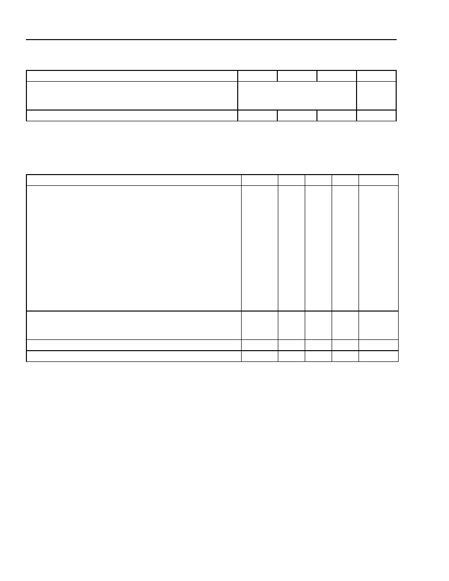
Parameter
Min
Typ
Max
Unit
Calculated MTBF (IO = 80% of IO, max; TC = 40 °C):
QW050F1
QW075F1
4,000,000
3,600,000
hours
Weight
—
75 (2.7)
g (oz.)
Parameter
Symbol
Min
Typ
Max
Unit
Remote On/Off Signal Interface
(VI = 0 V to 75 V; open collector or equivalent compatible;
Feature Descriptions.):
Logic Low—Module On
Logic High—Module Off
Logic Low:
At Ion/off = 1.0 mA
At Von/off = 0.0 V
Logic High:
At Ion/off = 0.0 A
Leakage Current
(IO = 80% of IO, max; VO within ±1% of steady state)
Von/off
Ion/off
Von/off
Ion/off
—
0
—
20
1.2
1.0
15
50
35
V
mA
V
A
ms
Output Voltage Adjustment (See Feature Descriptions.):
Output Voltage Remote-sense Range
Output Voltage Set-point Adjustment Range (trim)
—
60
—
0.5
110
V
%VO, nom
Output Overvoltage Protection
VO, sd
3.8*
—
4.5*
V
Overtemperature Protection
TC
—105
—
°C
相关PDF资料 |
PDF描述 |
|---|---|
| R-26 | INTERCONNECTION DEVICE |
| R1100D091C-TR-F | 0.9 V FIXED POSITIVE LDO REGULATOR, 0.75 V DROPOUT, PDSO3 |
| R1100D111C-TR-F | 1.1 V FIXED POSITIVE LDO REGULATOR, 0.6 V DROPOUT, PDSO3 |
| R1100D121C-TR-F | 1.2 V FIXED POSITIVE LDO REGULATOR, 0.6 V DROPOUT, PDSO3 |
| R1100D141C-TR-F | 1.4 V FIXED POSITIVE LDO REGULATOR, 0.4 V DROPOUT, PDSO3 |
相关代理商/技术参数 |
参数描述 |
|---|---|
| QW051 | 制造商:NTE Electronics 功能描述:Res Metal Film 51 Ohm 2% 1/4W ±200ppm/°C Conformal AXL Thru-Hole |
| QW051-10 | 制造商:NTE Electronics 功能描述: |
| QW0511BR | 制造商:NTE Electronics 功能描述:1/4 Watt, Rn 55D, 511 Ohm 1% Metal Film Resistor- 25/Pkg |
| QW051-BULK | 制造商:NTE Electronics 功能描述: |
| QW0523BR | 制造商:NTE Electronics 功能描述:1/4 Watt, Rn 55D, 523 Ohm 1% Metal Film Resistor- 25/Pkg |
发布紧急采购,3分钟左右您将得到回复。