- 您现在的位置:买卖IC网 > PDF目录296949 > R1283Z1A-E2 (RICOH COMPANY LTD) DC-DC REG PWR SUPPLY MODULE PDF资料下载
参数资料
| 型号: | R1283Z1A-E2 |
| 厂商: | RICOH COMPANY LTD |
| 元件分类: | 电源模块 |
| 英文描述: | DC-DC REG PWR SUPPLY MODULE |
| 封装: | 1.50 X 2.40 MM, WLCSP-11 |
| 文件页数: | 2/22页 |
| 文件大小: | 416K |
| 代理商: | R1283Z1A-E2 |
R1283x
10
There are also two operation modes for the PWM control inverting switching regulator, that is the continuous
mode and the discontinuous mode.
When the LX Tr. is on, the voltage for the inductor L will be VIN. The inductor current (IL1) will be;
IL1 = VIN×Ton / L..................................................................................................................Formula8
Inverting circuit saves energy during on time of Lx Tr,and supplies the energy to output during off time,output
voltage opposed to input voltage is obtained. The inductor current at off (IL2) will be;
IL2 = VOUT×Tf / L .................................................................................................................Formula9
(The above formula and after, the absolute value of the negative output voltage is assumed to be
VOUT.
:Output voltage= -10V ,VOUT=10 )
In terms of the PWM control, when the Tf=Toff, the inductor current will be continuous, the operation of the
switching regulator will be continuous mode.
In the continuous mode, the current variation of IL1 and IL2 are same, therefore
VIN×Ton / L = VOUT×Toff / L .................................................................................................Formula10
In the continuous mode, the duty cycle will be:
DUTY = Ton / (Ton+Toff) = VOUT / (VOUT + VIN )......................................................................Formula11
If the input power equals to output power,
IOUT = VIN
2×Ton / (2×L×V
OUT) ............................................................................................Formula12
When IOUT becomes more then Formula12 ,it will be continuous mode.
In this moment ,the peak current,Ilxmax flowing through the inductor is described as follows:
ILxmax = IOUT×VOUT / VIN + VIN×Ton / (2×L)........................................................................Formula13
ILxmax = IOUT×VOUT / VIN + VIN×VOUT×T / { 2×L×(VOUT + VIN ) }........................................Formula14
Therefore,peak current is more than IOUT.Considering the value of Ilxmax,the condition of input and
output,and external components should be selected.
The explanation above is based on the ideal calculation,and the loss caused by Lx switch and external
components is not included.
The actual maximum output current is between 50% and 80% of the calculation.
Especially,when the IL is large,or VIN is low,the loss of VIN is generated with on resistance of the switch.As
for VOUT,VF(as much as 0.3V)of the diode should be considered.
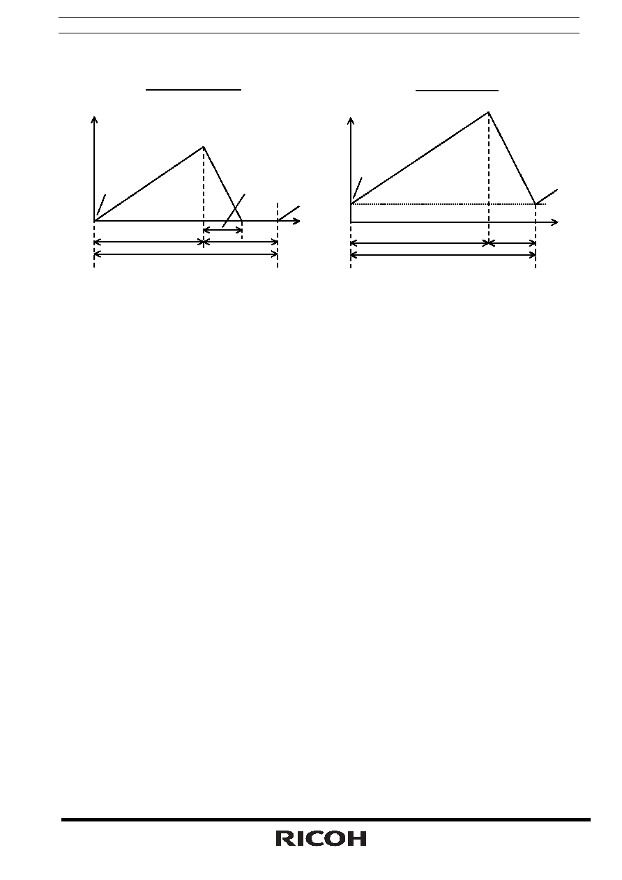
Discontinuous Mode
ILxmax
ILxmin
Ton
Toff
T=1/fosc
Tf
IL
t
ILxmax
ILxmin
Ton
Toff
T=1/fosc
t
IL
Continuous Mode
<
Current through L>
相关PDF资料 |
PDF描述 |
|---|---|
| R1285L591A | SWITCHING REGULATOR, 1600 kHz SWITCHING FREQ-MAX, DSO12 |
| R1285L273A | SWITCHING REGULATOR, 1600 kHz SWITCHING FREQ-MAX, DSO12 |
| R1285L311A | SWITCHING REGULATOR, 1600 kHz SWITCHING FREQ-MAX, DSO12 |
| R1285L462A | SWITCHING REGULATOR, 1600 kHz SWITCHING FREQ-MAX, DSO12 |
| R1285L221A | SWITCHING REGULATOR, 1600 kHz SWITCHING FREQ-MAX, DSO12 |
相关代理商/技术参数 |
参数描述 |
|---|---|
| R128405161 | 功能描述:RF 连接器 EMB M DR P-FIT E C C100 RoHS:否 制造商:Bomar Interconnect 产品:Connectors 射频系列:BNC 型式:Jack (Female) 极性: 触点电镀:Gold 阻抗: 端接类型:Solder 主体类型:Straight Bulkhead 电缆类型: |
| R128405161W | 功能描述:RF 连接器 EMB M DR P-FIT E C RoHS:否 制造商:Bomar Interconnect 产品:Connectors 射频系列:BNC 型式:Jack (Female) 极性: 触点电镀:Gold 阻抗: 端接类型:Solder 主体类型:Straight Bulkhead 电缆类型: |
| R128414701 | 制造商:Radiall 功能描述:EMB PLAT CAR C50 - Bulk |
| R128424848 | 功能描述:RF 连接器 BMA(M) STR SMT RCPT RoHS:否 制造商:Bomar Interconnect 产品:Connectors 射频系列:BNC 型式:Jack (Female) 极性: 触点电镀:Gold 阻抗: 端接类型:Solder 主体类型:Straight Bulkhead 电缆类型: |
| R128424848W | 功能描述:RF 连接器 EMB M DR CMS RoHS:否 制造商:Bomar Interconnect 产品:Connectors 射频系列:BNC 型式:Jack (Female) 极性: 触点电镀:Gold 阻抗: 端接类型:Solder 主体类型:Straight Bulkhead 电缆类型: |
发布紧急采购,3分钟左右您将得到回复。