- 您现在的位置:买卖IC网 > PDF目录69309 > R5F21354CDFP 8-BIT, FLASH, 20 MHz, MICROCONTROLLER, PQFP52 PDF资料下载
参数资料
| 型号: | R5F21354CDFP |
| 元件分类: | 微控制器/微处理器 |
| 英文描述: | 8-BIT, FLASH, 20 MHz, MICROCONTROLLER, PQFP52 |
| 封装: | 10 X 10 MM, 0.65 MM PITCH, PLASTIC, LQFP-52 |
| 文件页数: | 12/29页 |
| 文件大小: | 632K |
| 代理商: | R5F21354CDFP |
第1页第2页第3页第4页第5页第6页第7页第8页第9页第10页第11页当前第12页第13页第14页第15页第16页第17页第18页第19页第20页第21页第22页第23页第24页第25页第26页第27页第28页第29页
R8C/35C Group
1. Overview
REJ03B0283-0001 Rev.0.01 Sep. 01, 2009
Page 2 of 27
Under development Preliminary specification
Specifications in this manual are tentative and subject to change.
1.1.2
Specifications
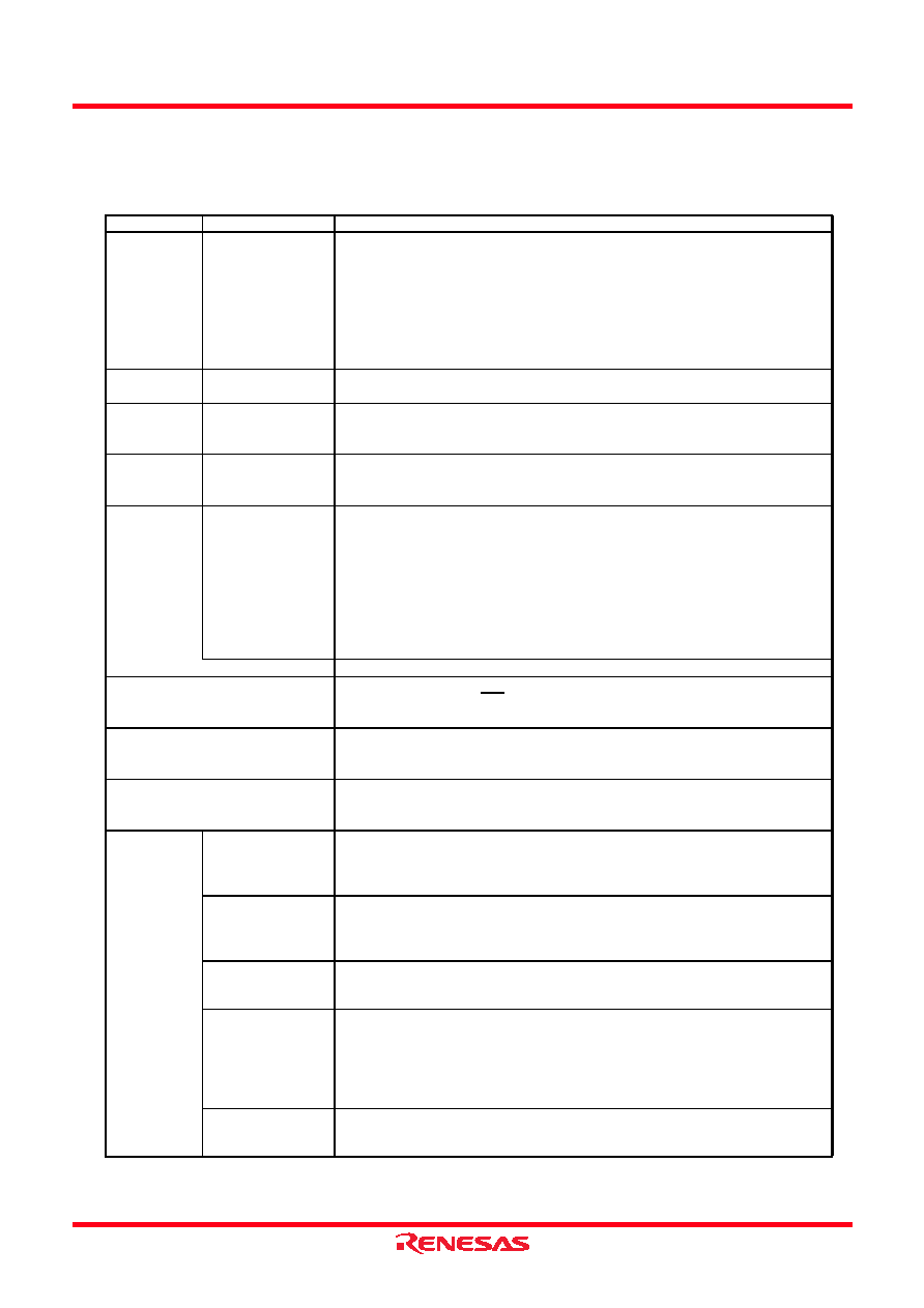
Table 1.1
Specifications for R8C/35C Group (1)
Item
Function
Specification
CPU
Central processing
unit
R8C CPU core
Number of fundamental instructions: 89
Minimum instruction execution time:
50 ns (f(XIN) = 20 MHz, VCC = 2.7 to 5.5 V)
200 ns (f(XIN) = 5 MHz, VCC = 1.8 to 5.5 V)
Multiplier: 16 bits × 16 bits
→ 32 bits
Multiply-accumulate instruction: 16 bits × 16 bits + 32 bits
→ 32 bits
Operation mode: Single-chip mode (address space: 1 Mbyte)
Memory
ROM, RAM, Data
flash
Refer to Table 1.3 Product List for R8C/35C Group.
Power Supply
Voltage
Detection
Voltage detection
circuit
Power-on reset
Voltage detection 3 (detection level of voltage detection 0 and voltage
detection 1 selectable)
I/O Ports
Programmable I/O
ports
Input-only: 1 pin
CMOS I/O ports: 47, selectable pull-up resistor
High current drive ports: 47
Clock
Clock generation
circuits
4 circuits: XIN clock oscillation circuit,
XCIN clock oscillation circuit (32 kHz),
High-speed on-chip oscillator (with frequency adjustment function),
Low-speed on-chip oscillator
Oscillation stop detection: XIN clock oscillation stop detection function
Frequency divider circuit: Dividing selectable 1, 2, 4, 8, and 16
Low power consumption modes:
Standard operating mode (high-speed clock, low-speed clock, high-speed
on-chip oscillator, low-speed on-chip oscillator), wait mode, stop mode
Real-time clock (timer RE)
Interrupts
Number of interrupt vectors: 69
External Interrupt: 9 (INT × 5, Key input × 4)
Priority levels: 7 levels
Watchdog Timer
14 bits × 1 (with prescaler)
Reset start selectable
Low-speed on-chip oscillator for watchdog timer selectable
DTC (Data Transfer Controller)
1 channel
Activation sources: 33
Transfer modes: 2 (normal mode, repeat mode)
Timer
Timer RA
8 bits × 1 (with 8-bit prescaler)
Timer mode (period timer), pulse output mode (output level inverted every
period), event counter mode, pulse width measurement mode, pulse period
measurement mode
Timer RB
8 bits × 1 (with 8-bit prescaler)
Timer mode (period timer), programmable waveform generation mode (PWM
output), programmable one-shot generation mode, programmable wait one-
shot generation mode
Timer RC
16 bits × 1 (with 4 capture/compare registers)
Timer mode (input capture function, output compare function), PWM mode
(output 3 pins), PWM2 mode (PWM output pin)
Timer RD
16 bits × 2 (with 4 capture/compare registers)
Timer mode (input capture function, output compare function), PWM mode
(output 6 pins), reset synchronous PWM mode (output three-phase
waveforms (6 pins), sawtooth wave modulation), complementary PWM mode
(output three-phase waveforms (6 pins), triangular wave modulation), PWM3
mode (PWM output 2 pins with fixed period)
Timer RE
8 bits × 1
Real-time clock mode (count seconds, minutes, hours, days of week), output
compare mode
相关PDF资料 |
PDF描述 |
|---|---|
| R5F21364CDFP | 8-BIT, FLASH, 20 MHz, MICROCONTROLLER, PQFP64 |
| R5F2136CCNFP | 8-BIT, FLASH, 20 MHz, MICROCONTROLLER, PQFP64 |
| R5F2136CCDFP | 8-BIT, FLASH, 20 MHz, MICROCONTROLLER, PQFP64 |
| R5F21366CNFP | 8-BIT, FLASH, 20 MHz, MICROCONTROLLER, PQFP64 |
| R5F21368CNFP | 8-BIT, FLASH, 20 MHz, MICROCONTROLLER, PQFP64 |
相关代理商/技术参数 |
参数描述 |
|---|---|
| R5F21354CDFP#U0 | 制造商:Renesas Electronics Corporation 功能描述:MCU 16-Bit R8C CISC 16KB Flash 3.3V/5V 52-Pin LQFP Tube 制造商:Renesas Electronics Corporation 功能描述:R8C35C 16+4KB 1.8/5.5V -40 85C 52LQFP - Trays |
| R5F21354CDFP#V0 | 功能描述:MCU 16KB ROM 1.5KB RAM 52-LQFP RoHS:是 类别:集成电路 (IC) >> 嵌入式 - 微控制器, 系列:R8C/3x/35C 标准包装:250 系列:80C 核心处理器:8051 芯体尺寸:8-位 速度:16MHz 连通性:EBI/EMI,I²C,UART/USART 外围设备:POR,PWM,WDT 输入/输出数:40 程序存储器容量:- 程序存储器类型:ROMless EEPROM 大小:- RAM 容量:256 x 8 电压 - 电源 (Vcc/Vdd):4.5 V ~ 5.5 V 数据转换器:A/D 8x10b 振荡器型:内部 工作温度:-40°C ~ 85°C 封装/外壳:68-LCC(J 形引线) 包装:带卷 (TR) |
| R5F21354CDFP#V2 | 制造商:Renesas Electronics Corporation 功能描述:R8C/35C 16K+4K/1.5K 52LQFP 10X10 -40-+85 - Trays |
| R5F21354CNFP | 制造商:RENESAS 制造商全称:Renesas Technology Corp 功能描述:RENESAS MCU |
| R5F21354CNFP#U0 | 制造商:Renesas Electronics Corporation 功能描述:FDC35C 16+4KB 1.8/5.5V -20 85C 制造商:Renesas Electronics Corporation 功能描述:R8C35C 16+4KB 1.8/5.5V -20 85C 52LQFP - Trays |
发布紧急采购,3分钟左右您将得到回复。