- 您现在的位置:买卖IC网 > PDF目录69310 > R5F2L35ACDFP 8-BIT, FLASH, 20 MHz, MICROCONTROLLER, PQFP52 PDF资料下载
参数资料
| 型号: | R5F2L35ACDFP |
| 元件分类: | 微控制器/微处理器 |
| 英文描述: | 8-BIT, FLASH, 20 MHz, MICROCONTROLLER, PQFP52 |
| 封装: | 10 X 10 MM, 0.65 MM PITCH, PLASTIC, LQFP-52 |
| 文件页数: | 30/34页 |
| 文件大小: | 882K |
| 代理商: | R5F2L35ACDFP |
第1页第2页第3页第4页第5页第6页第7页第8页第9页第10页第11页第12页第13页第14页第15页第16页第17页第18页第19页第20页第21页第22页第23页第24页第25页第26页第27页第28页第29页当前第30页第31页第32页第33页第34页
R8C/L35C Group, R8C/L36C Group, R8C/L38C Group, R8C/L3AC Group
1. Overview
R01DS0095EJ0101 Rev.1.01
Page 5 of 72
Apr 15, 2011
Note:
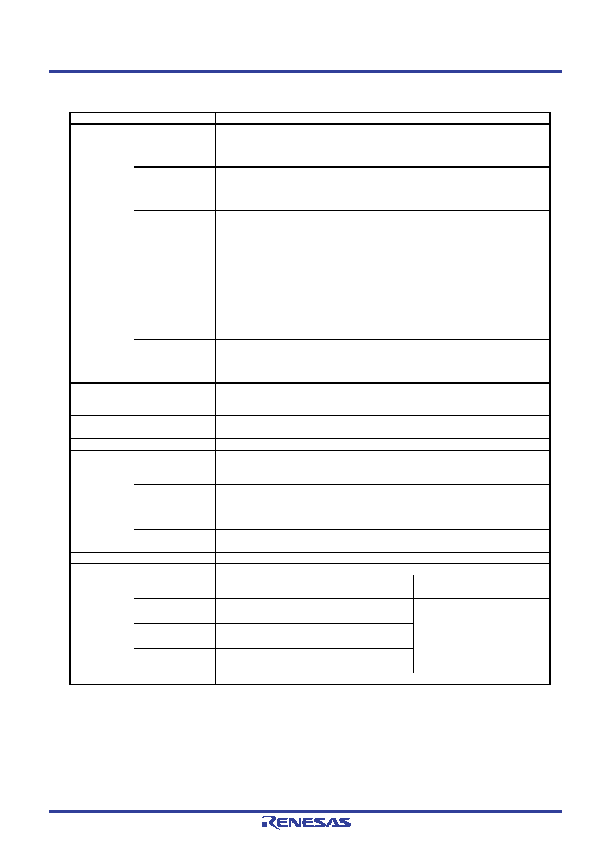
1. This applies when four pins are selected for common output.
Table 1.5
Specifications (2)
Item
Function
Specification
Timer
Timer RA
8 bits × 1 (with 8-bit prescaler)
Timer mode (period timer), pulse output mode (output level inverted every
period), event counter mode, pulse width measurement mode,
pulse period measurement mode
Timer RB
8 bits × 1 (with 8-bit prescaler)
Timer mode (period timer), programmable waveform generation mode (PWM
output), programmable one-shot generation mode, programmable wait one-
shot generation mode
Timer RC
16 bits × 1 (with 4 capture/compare registers)
Timer mode (input capture function, output compare function), PWM mode
(output: 3 pins), PWM2 mode (PWM output: 1 pin)
Timer RD
16 bits × 2 (with 4 capture/compare registers)
Timer mode (input capture function, output compare function), PWM mode
(output: 6 pins), reset synchronous PWM mode (three-phase waveform output:
6 pins, sawtooth wave modulation), complementary PWM mode (three-phase
waveform output: 6 pins, triangular wave modulation), PWM3 mode (PWM
output with fixed period: 2 pins)
Timer RE
8 bits × 1
Real-time clock mode (counting of seconds, minutes, hours, days of week),
output compare mode
Timer RG
16 bits × 1
Phase-counting mode,
timer mode (output compare function, input capture function),
PWM mode (output: 1 pin)
Serial
Interface
UART0, UART1
Clock synchronous serial I/O/UART × 2 channels
UART2
Clock synchronous serial I/O/UART, I2C mode (I2C-bus),
multiprocessor communication function
Synchronous Serial
Communication Unit (SSU)
1 (shared with I2C-bus)
I2C bus
1 (shared with SSU)
LIN Module
Hardware LIN: 1 channel (timer RA, UART0 used)
A/D
Converter
R8C/L35C Group
10-bit resolution × 10 channels, including sample and hold function, with sweep
mode
R8C/L36C Group
10-bit resolution × 10 channels, including sample and hold function, with sweep
mode
R8C/L38C Group
10-bit resolution × 16 channels, including sample and hold function, with sweep
mode
R8C/L3AC Group
10-bit resolution × 20 channels, including sample and hold function, with sweep
mode
D/A Converter
8-bit resolution × 2 circuits
Comparator B
2 circuits
LCD Drive
Control
Circuit
R8C/L35C Group
Common output: Max. 4 pins
Segment output: Max. 24 pins
Bias: 1/2, 1/3
Duty: static, 1/2, 1/3, 1/4
R8C/L36C Group
Common output: Max. 8 pins
Segment output: Max. 32 pins (1)
Bias: 1/2, 1/3, 1/4
Duty: static, 1/2, 1/3, 1/4, 1/8
R8C/L38C Group
Common output: Max. 8 pins
Segment output: Max. 48 pins (1)
R8C/L3AC Group
Common output: Max. 8 pins
Segment output: Max. 56 pins (1)
Voltage multiplier and dedicated regulator integrated
相关PDF资料 |
PDF描述 |
|---|---|
| R5F2L368ANFA | 8-BIT, FLASH, 20 MHz, MICROCONTROLLER, PQFP64 |
| R5F2L3ACADFA | 8-BIT, FLASH, 20 MHz, MICROCONTROLLER, PQFP100 |
| R5F2L388ANFP | 8-BIT, FLASH, 20 MHz, MICROCONTROLLER, PQFP80 |
| R5F2L388ADFA | 8-BIT, FLASH, 20 MHz, MICROCONTROLLER, PQFP80 |
| R5F2L388BDFP | 8-BIT, FLASH, 20 MHz, MICROCONTROLLER, PQFP80 |
相关代理商/技术参数 |
参数描述 |
|---|---|
| R5F2L35ACDFP#30 | 制造商:Renesas Electronics Corporation 功能描述:IC MCU 16BIT 96KB FLASH 52LQFP |
| R5F2L35ACDFP#U0 | 功能描述:MCU 96KB ROM 10KB RAM 52-LQFP RoHS:是 类别:集成电路 (IC) >> 嵌入式 - 微控制器, 系列:R8C/Lx/35C 标准包装:250 系列:80C 核心处理器:8051 芯体尺寸:8-位 速度:16MHz 连通性:EBI/EMI,I²C,UART/USART 外围设备:POR,PWM,WDT 输入/输出数:40 程序存储器容量:- 程序存储器类型:ROMless EEPROM 大小:- RAM 容量:256 x 8 电压 - 电源 (Vcc/Vdd):4.5 V ~ 5.5 V 数据转换器:A/D 8x10b 振荡器型:内部 工作温度:-40°C ~ 85°C 封装/外壳:68-LCC(J 形引线) 包装:带卷 (TR) |
| R5F2L35ACDFP#U1 | 制造商:Renesas Electronics Corporation 功能描述: |
| R5F2L35ACDFP#V2 | 制造商:Renesas Electronics Corporation 功能描述:R8C/L35C 96K+4K/10K 52LQFP 10X10 -40-+85 - Trays |
| R5F2L35ACNFP#30 | 制造商:Renesas Electronics Corporation 功能描述:IC MCU 16BIT 96KB FLASH 52LQFP |
发布紧急采购,3分钟左右您将得到回复。