- 您现在的位置:买卖IC网 > PDF目录192170 > RB105-DB (FUJI ELECTRIC CO LTD) POWER/SIGNAL RELAY, SPST, MOMENTARY, 0.017A (COIL), 12VDC (COIL), 200mW (COIL), 5A (CONTACT), 30VDC (CONTACT), THROUGH HOLE-STRAIGHT MOUNT PDF资料下载
参数资料
| 型号: | RB105-DB |
| 厂商: | FUJI ELECTRIC CO LTD |
| 元件分类: | 功率/信号继电器 |
| 英文描述: | POWER/SIGNAL RELAY, SPST, MOMENTARY, 0.017A (COIL), 12VDC (COIL), 200mW (COIL), 5A (CONTACT), 30VDC (CONTACT), THROUGH HOLE-STRAIGHT MOUNT |
| 文件页数: | 1/1页 |
| 文件大小: | 66K |
| 代理商: | RB105-DB |
Fuji Electric FA Components & Systems Co., Ltd./D & C Catalog
Information subject to change without notice
03/15
03
Type
Ordering
Power
Rated
Pick-up
Thermal
Make and
code
consumption
voltage
current
break current
(res.load)
RB104
RB104-
■
120mW
4.5, 5, 6
70% of rated
5A
5A at 250V AC
RB105
RB105-
■
200mW
24V DC
voltage or less
5A at 30V DC
DC operated slim type card relays
Rated thermal currrent 5 Amps.
■ Description
The RB104 and 105 relays are designed
for printed circuit board use.
These relays are extremely thin (5mm)
and so, can be densely mounted on PC
boards. As a result, PC board size and
cost can be greatly reduced.
Employing of bifurcated contacts
ensure high contact reliability, allowing
the RB104,105 relays to be used in low-
level circuits.
Coil voltages are available in ranges
from 4.5V to 24V DC.
■ Types and ratings
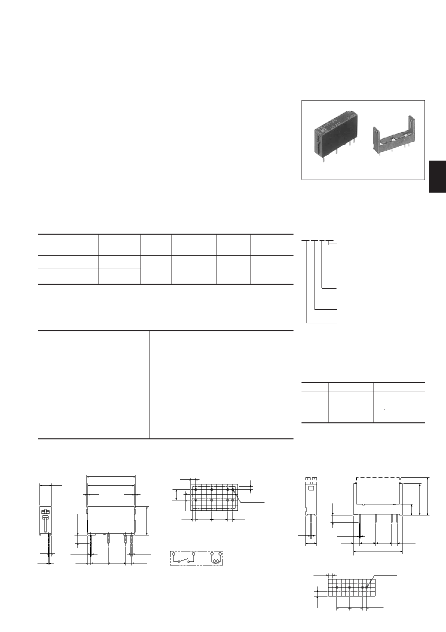
■ Dimensions, mm
PC board drilling (View from back side)
Internal wiring diagram
RB 10 4-DE
■ Type number nomenenclature
Industrial Control Relays
Card relay RB104,105
Mass: 3g
RB105
■ Ordering information
Specify the following:
1. Type number
AF93-205
Socket TP04
AF95-567
■ Features
Thin, miniature size and light weight
The mounting space on the PC board
can be reduced.
UL, CSA and TV approved
Low power consumption
They can be operated by means of
non-polarity magnet.
SIL terminal arrangement
SIL (Single-side In-Line lead) package
allows the relays to be mounted easily
on PC board.
Fluxtight construction
Immersion cleanable
RB104,105
Socket TP04
Voltage
120V AC
240V AC
30V DC
120V DC
Resistive load
Inductive load
–
5A
0.5A
1A
–
2A (15ms)
0.2A (15ms)
Ratings
■ Approvals
UL, CSA and TV
UL file No. E44592
CSA file No. LR20479
TV license No. R9551729
Note: Enter the coil voltage code in the
■ mark as follow
4.5V DC: DC, 5V DC: DY, 6V DC: DA, 9V DC: DD, 12V DC: DB, 24V DC: DE
Operating time
Release time
Dielectric strength
Stray electrostatic capacity
Impulse
Insulation resistance
Electrical durability
AC
DC
Mechanical durability
Ambient temperature
10ms or less at rated voltage
5ms or less at rated voltage
750V AC rms. 1 min. between open contacts
2,000V AC rms. 1 min. between contact and coil
Approx. 1.4pF between contact and coil
4,500V or more 1.2 × 50s between contact and coil
100M at 500V DC megger
100,000 operations at 220V AC 2A, inductive load
130,000 operations at 220V AC 3A, resistive load
150,000 operations at 24V DC 1A, inductive load
100,000 operations at 24V DC 5A, resistive load
20 million operations
–40°C to +70°C(no icing)
■ Specifications
Operating coil voltage
DC: 4.5 V DC
DY: 5V DC
DA: 6V DC
DD: 9V DC
DB: 12V DC
DE: 24V DC
Watt loss
4: 120mW
5: 200mW
Contact arrengement
10: 1NO
Basic type
5.08 max
21.3 max
20
0.5
1
0.3
2-0.7
1.3
7.62
2.54
2-0.5
3.8
max
12.6
max
5
0.3
3.5
2.54
7.62
22.2
2.4
0.7
5
14.2
17
9, 12
1.3
7.62
2.54
4-1.2 ±0.1
2.54
1
2.54
5.08
4-1.2±0.1
7.62 7.62
2.54
PC board drilling (View from back side)
相关PDF资料 |
PDF描述 |
|---|---|
| RB105-DC | POWER/SIGNAL RELAY, SPST, MOMENTARY, 0.044A (COIL), 4.5VDC (COIL), 200mW (COIL), 5A (CONTACT), 30VDC (CONTACT), THROUGH HOLE-STRAIGHT MOUNT |
| RB105-DD | POWER/SIGNAL RELAY, SPST, MOMENTARY, 0.022A (COIL), 9VDC (COIL), 200mW (COIL), 5A (CONTACT), 30VDC (CONTACT), THROUGH HOLE-STRAIGHT MOUNT |
| RB105-DE | POWER/SIGNAL RELAY, SPST, MOMENTARY, 0.008A (COIL), 24VDC (COIL), 200mW (COIL), 5A (CONTACT), 30VDC (CONTACT), THROUGH HOLE-STRAIGHT MOUNT |
| RB105-DY | POWER/SIGNAL RELAY, SPST, MOMENTARY, 0.04A (COIL), 5VDC (COIL), 200mW (COIL), 5A (CONTACT), 30VDC (CONTACT), THROUGH HOLE-STRAIGHT MOUNT |
| RB1203 | COPPER ALLOY, TIN FINISH, FORK TERMINAL |
相关代理商/技术参数 |
参数描述 |
|---|---|
| RB105-DD | 制造商:Fuji Electric 功能描述: |
| RB105-DE | 制造商:Fuji Electric 功能描述:Electromechanical Relay SPST-NO 5A 24VDC Through Hole |
| RB105-DY | 制造商:Fuji Electric 功能描述:Electromechanical Relay SPST-NO 5A 5VDC Through Hole |
| RB10B | 制造商:Superior Electric 功能描述:REPLACEMENT BRUSH FOR THE 10C TRANSFORMER |
| RB10B/RB10C | 制造商:Superior Electric 功能描述:Replacement Brush Assembly; Variable transformer; alt part# 030098-001 |
发布紧急采购,3分钟左右您将得到回复。