- 您现在的位置:买卖IC网 > PDF目录378123 > RC2204 (Electronic Theatre Controls, Inc.) ZigBee Ready RF Transceiver Modules PDF资料下载
参数资料
| 型号: | RC2204 |
| 厂商: | Electronic Theatre Controls, Inc. |
| 英文描述: | ZigBee Ready RF Transceiver Modules |
| 中文描述: | 的ZigBee功能的RF收发模块 |
| 文件页数: | 8/17页 |
| 文件大小: | 372K |
| 代理商: | RC2204 |
JTAG Interface
The module offers a JTAG interface for Flash and EEPROM programming, as well as for
debugging.
Programming through the JTAG interface requires control of the four JTAG specific pins:
TCK, TMS, TDI, and TDO. Control of the reset and clock pins is not normally required. To be
able to use the JTAG interface, the JTAGEN Fuse must be programmed. The device is
default shipped with the fuse programmed. For further information, please refer to the
respective MCU data sheet.
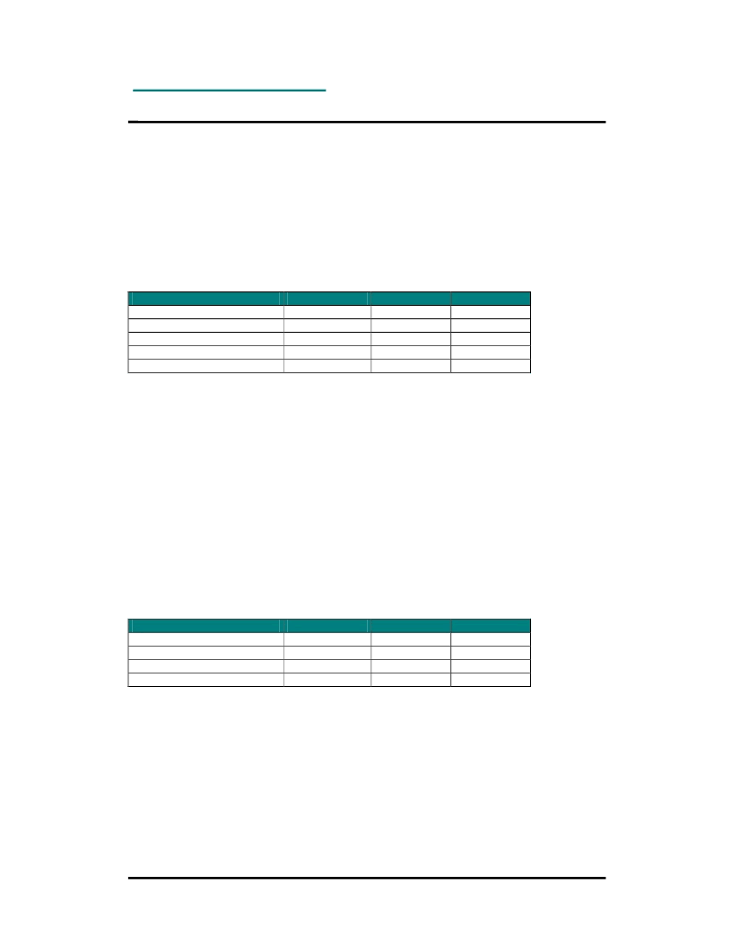
The table below show the JTAG pin mapping.
Signal
RC2200
TDI
12
TDO
13
TMS
14
TCK
15
RESET
44
Supply and ground must also be connected during programming.
ISP Interface
The module offers an In-System Programming (ISP) interface for Flash and EEPROM
memory programming. The fastest way to do firmware downloading in manufacturing is
through the ISP interface rather then the JTAG interface.
The memory arrays can be programmed using the serial interface bus while RESET is pulled
to GND. The serial interface consists of pins SCK, PDI/MOSI (input) and PDO/MISO (output).
The RC2200 and RC2204 use the PDI and PDO pins (shared with UART0), while RC2202
use MOSI and MISO (shared with SPI interface), see table below.
After RESET is set low, the Programming Enable instruction needs to be executed first before
program/erase operations can be executed. More information is available in the respective
MCU data sheets.
The table below show the pin mapping for ISP programming.
Signal
RC2200
PDI
21
PDO
22
SCL
36
RESET
44
Supply and ground must also be connected during programming.
RC220x
2005 Radiocrafts AS
RC220x Data Sheet (rev. 1.0)
Page 8 of 17
RC2202
12
13
14
15
44
RC2204
12
13
14
15
44
RC2202
37
38
36
44
RC2204
21
22
36
44
相关PDF资料 |
PDF描述 |
|---|---|
| RC2204AT | ZigBee Ready RF Transceiver Modules |
| RC2204MM | ZigBee Ready RF Transceiver Modules |
| RC220X | ZigBee Ready RF Transceiver Modules |
| RCA1000 | 8 AMPERE SILICON NPN DARLINGTON POWER TRANSISTORS |
| RCA1001 | 8 AMPERE SILICON NPN DARLINGTON POWER TRANSISTORS |
相关代理商/技术参数 |
参数描述 |
|---|---|
| RC2204AT | 制造商:未知厂家 制造商全称:未知厂家 功能描述:ZigBee Ready RF Transceiver Modules |
| RC2204M | 制造商:Thomas & Betts 功能描述:Tape Terminal |
| RC2204MM | 制造商:未知厂家 制造商全称:未知厂家 功能描述:ZigBee Ready RF Transceiver Modules |
| RC2207 | 制造商:Thomas & Betts 功能描述:RC2207 INS VINYL LKG FORK TERM, 制造商:Thomas & Betts 功能描述:INS VINYL LKG FORK TERM, 12-10, #6, 制造商:Thomas & Betts 功能描述:Fork Terminal 10-12AWG 27.68mm 7.87mm Electro-Tin Bulk |
发布紧急采购,3分钟左右您将得到回复。