- 您现在的位置:买卖IC网 > PDF目录230923 > RDC-634-H-3-A (DATA DEVICE CORP) SYNCHRO OR RESOLVER TO DIGITAL CONVERTER, DMA27 PDF资料下载
参数资料
| 型号: | RDC-634-H-3-A |
| 厂商: | DATA DEVICE CORP |
| 元件分类: | 位置变换器 |
| 英文描述: | SYNCHRO OR RESOLVER TO DIGITAL CONVERTER, DMA27 |
| 文件页数: | 4/7页 |
| 文件大小: | 121K |
| 代理商: | RDC-634-H-3-A |
4
Data Device Corporation
www.ddc-web.com
SDC-630/632/634
H-07/05-0
TECHNICAL INFORMATION
TIMING
FIGURE 2 shows the timing waveforms of the converter.
Whenever an input angle change occurs, the converter changes
the digital angle in steps of 1 LSB, and generates a converter
busy impulse (CB). The CB is a positive pulse 0.5 to 1.5sec
long. Data changes on the leading edge of the CB pulse, and
data can be transferred 0.5sec after the leading edge.
The simplest method of interfacing with a computer is to transfer
data at a fixed time interval after the inhibit is applied. The con-
verter will ignore an inhibit applied during the “busy” interval until
that interval is over. Timing is as follows: (a) apply the inhibit, (b)
wait 0.5sec, (c) transfer the data, and (d) release the inhibit.
Extra CB pulses will not occur if the input angle changes while
the counter is locked by the INH.
VALID
6.1
s MIN
DEPENDS ON d
θ
dt
0.5-1.5
s
.5
s
DATA
VALID
INHIBIT
(INH)
"1"
"0"
CONVERTER
BUSY (CB)
"1"
"0"
FIGURE 2. SDC-630/632/634 TIMING DIAGRAM
DYNAMIC PERFORMANCE
A type II servo loop (KV =
∞ ) and very high acceleration con-
stants give these converters superior dynamic performance, as
listed in the specifications. If the power supply voltages are not
the +15 VDC nominal values, the specified input rates for full
accuracy will increase or decrease in proportion to the fractional
change in voltage. The +15 V supply voltage will determine the
positive maximum velocity, and the -15 V supply voltage will
determine the negative maximum velocity.
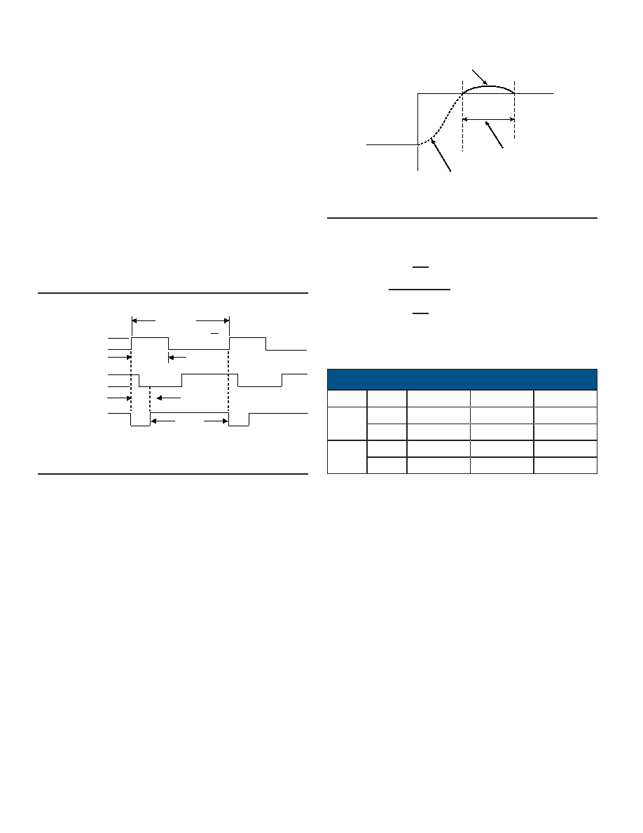
So long as the maximum tracking rate is not exceeded, there will
be no lag in the converter output. If a step input occurs, as is like-
ly when the power is initially turned on, the response will be crit-
ically damped. FIGURE 3 shows the response to a step input.
After initial slewing at the maximum tracking rate of the convert-
er, there is one overshoot which is inherent to a Type II servo.
The overshoot settling to a final value is a function of the small
signal settling time.
POWER SUPPLIES
The main power supplies can vary over their specified ranges
with no change in the converter specifications except for a pro-
portional change in the maximum tracking rates.
When testing or evaluating the converters, it is advisable to limit
the current to each of the three power supplies. Set each limit to
50% greater than the maximum current listed for that supply in
the specifications table.
TRANSFORMER INPUT
To prevent damage to the input transformers, the maximum
steady state voltage should not exceed the specified input volt-
age by more than 30%. The maximum common mode voltage
(DC plus recurrent AC peak) should not exceed 500 V.
SDC-630
400 Hz
A
190 sec-1
B
91 sec-1
60 Hz
A
46 sec-1
B
23 sec-1
SDC-632
226 sec-1
100 sec-1
58 sec-1
26 sec-1
SDC-634
167 sec-1
56 sec-1
30 sec-1
10 sec-1
OVERSHOOT
SMALL SIGNAL
SETTLING TIME
MAX SLOPE EQUALS
TRACKING RATE (SLEW RATE)
θ2
θ1
FIGURE 3. RESPONSE TO A STEP INPUT
A
2 (
+1)
G =
S
2 (
+1)
S
B
S
10B
The nominal open loop transfer function is given by
where the parameters A and B are:
TABLE 2. TRANSFER FUNCTION PARAMETERS
相关PDF资料 |
PDF描述 |
|---|---|
| RDC-632-M-1 | SYNCHRO OR RESOLVER TO DIGITAL CONVERTER, DMA27 |
| RDC-19229S-483Z | SYNCHRO OR RESOLVER TO DIGITAL CONVERTER, CQCC40 |
| RDC-19229-422L | SYNCHRO OR RESOLVER TO DIGITAL CONVERTER, CQCC44 |
| RD-14595D1-382Z | SYNCHRO OR RESOLVER TO DIGITAL CONVERTER, DIP36 |
| RD-14595D1-392Q | SYNCHRO OR RESOLVER TO DIGITAL CONVERTER, DIP36 |
相关代理商/技术参数 |
参数描述 |
|---|---|
| RDC-634-ST-H-1-AR | 制造商:未知厂家 制造商全称:未知厂家 功能描述:Converter |
| RDC-634-ST-H-1-R | 制造商:未知厂家 制造商全称:未知厂家 功能描述:Resolver-to-Digital Converter |
| RDC-634-ST-H-3-AR | 制造商:未知厂家 制造商全称:未知厂家 功能描述:Converter |
| RDC-634-ST-H-3-R | 制造商:未知厂家 制造商全称:未知厂家 功能描述:Resolver-to-Digital Converter |
| RDC-634-ST-L-1-AR | 制造商:未知厂家 制造商全称:未知厂家 功能描述:Converter |
发布紧急采购,3分钟左右您将得到回复。