- 您现在的位置:买卖IC网 > PDF目录11292 > RDER72J682K2M1C11A (Murata Electronics North America)CAP CER 6800PF 630V 10% RADIAL PDF资料下载
参数资料
| 型号: | RDER72J682K2M1C11A |
| 厂商: | Murata Electronics North America |
| 文件页数: | 18/57页 |
| 文件大小: | 0K |
| 描述: | CAP CER 6800PF 630V 10% RADIAL |
| 标准包装: | 2,000 |
| 系列: | RDE |
| 电容: | 6800pF |
| 电压 - 额定: | 630V |
| 容差: | ±10% |
| 温度系数: | X7R |
| 安装类型: | 通孔 |
| 工作温度: | -55°C ~ 125°C |
| 应用: | 通用 |
| 封装/外壳: | 径向 |
| 尺寸/尺寸: | 0.197" L x 0.124" W(5.00mm x 3.15mm) |
| 高度 - 座高(最大): | 0.197"(5.00mm) |
| 引线间隔: | 0.197"(5.00mm) |
| 包装: | 带盒(TB) |
| 引线型: | 纽结 |
第1页第2页第3页第4页第5页第6页第7页第8页第9页第10页第11页第12页第13页第14页第15页第16页第17页当前第18页第19页第20页第21页第22页第23页第24页第25页第26页第27页第28页第29页第30页第31页第32页第33页第34页第35页第36页第37页第38页第39页第40页第41页第42页第43页第44页第45页第46页第47页第48页第49页第50页第51页第52页第53页第54页第55页第56页第57页
�� �
�
�!� Note� ?� Please� read� rating� and� !� CAUTION� (for� storage,� operating,� rating,� soldering,� mounting� and� handling)� in� this� catalog� to� prevent� smoking� and/or� burning,� etc.�
�?� This� catalog� has� only� typical� speci?cations.� Therefore,� please� approve� our� product� speci?cations� or� transact� the� approval� sheet� for� product� speci?cations� before� ordering.�
�C49E.pdf�
�Mar.12,2014�
�1�
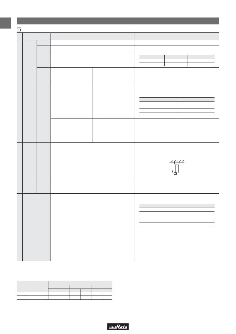
�Temperature� Compensating� Type� Speci?cations� and� Test� Methods�
�Continued� from� the� preceding� page.�
�No.� AEC-Q200� Test� Item�
�Specifications�
�AEC-Q200� Test� Method�
�Appearance� No� defects� or� abnormalities�
�Capacitance� Within� the� specified� tolerance�
�Visual� inspection.�
�The� capacitance,� Q� should� be� measured� at� 25°C� at� the�
�Q�
�30pF� V� C:� Q� U� 1,000�
�30pF� G� C:� Q� U� 400+20C�
�C:� Nominal� Capacitance� (pF)�
�frequency� and� voltage� shown� in� the� table.�
�Nominal� Cap.� Frequency� Voltage�
�C� V� 1000pF� 1±0.1MHz� AC0.5� to� 5V� (r.m.s.)�
�C� G� 1000pF� 1±0.1kHz� AC1±0.2V� (r.m.s.)�
�I.R.�
�Between� Terminals�
�10,000M� Ω� or� 500M� Ω� ·� μF� min.�
�(Whichever� is� smaller)�
�The� insulation� resistance� should� be� measured� with� a� DC�
�voltage� not� exceeding� the� rated� voltage� at� 25°C� within� 2min.�
�of� charging.�
�The� capacitor� should� not� be� damaged� when� DC� voltage�
�Electrical�
�17� Charac-�
�terization�
�shown� in� the� table� is� applied� between� the� terminations�
�for� 1� to� 5� seconds.�
�(Charge/Discharge� current� V� 50mA.)�
�Dielectric�
�Strength�
�Between� Terminals�
�No� defects� or� abnormalities�
�Rated� Voltage�
�DC50V,� DC100V�
�DC250V�
�DC630V�
�DC1kV�
�Test� Voltage�
�300%� of� the� rated� voltage�
�200%� of� the� rated� voltage�
�150%� of� the� rated� voltage�
�130%� of� the� rated� voltage�
�The� capacitor� is� placed� in� a� container� with� metal� balls� of� 1mm�
�diameter� so� that� each� terminal,� short-circuit� is� kept�
�Body� Insulation�
�No� defects� or� abnormalities�
�approximately� 2mm� from� the� balls,� and� 250%� of� the� rated� DC�
�voltage� is� impressed� for� 1� to� 5� seconds� between� capacitor�
�terminals� and� metal� balls.�
�(Charge/Discharge� current� V� 50mA.)�
�As� in� the� figure,� fix� the� capacitor� body,� apply� the� force�
�gradually� to� each� lead� in� the� radial� direction� of� the� capacitor�
�until� reaching� 10N� and� then� keep� the� force� applied� for�
�18�
�Terminal�
�Strength�
�Tensile�
�Strength�
�Bending�
�Strength�
�Termination� not� to� be� broken� or� loosened�
�Termination� not� to� be� broken� or� loosened�
�10±1� seconds.�
�F�
�Each� lead� wire� should� be� subjected� to� a� force� of� 2.5N� and� then�
�be� bent� 90°� at� the� point� of� egress� in� one� direction.� Each� wire� is�
�then� returned� to� the� original� position� and� bent� 90°� in� the�
�opposite� direction� at� the� rate� of� one� bend� per� 2� to� 3� seconds.�
�The� capacitance� change� should� be� measured� after� 5min.� at�
�each� specified� temperature� step.�
�Step�
�Temperature� (°C)�
�1�
�25±2�
�2�
�-55±3�
�3�
�25±2�
�Within� the� specified� Tolerance.�
�4�
�125±3�
�Capacitance�
�(Table� A)�
�5�
�25±2�
�19� Temperature�
�Characteristics�
�Capacitance� Drift� is� within� ±0.2%� or� ±0.05pF�
�(Whichever� is� larger)�
�The� temperature� coefficient� is� determind� using� the� capacitance�
�measured� in� step� 3� as� a� reference.� When� cycling� the�
�temperature� sequentially� from� step� 1� through� 5� (-55°C� to�
�+125°C)� the� capacitance� should� be� within� the� specified�
�tolerance� for� the� temperature� coefficient� and� capacitance�
�change� as� Table� A.�
�The� capacitance� drift� is� caluculated� by� dividing� the� differences�
�betweeen� the� maximum� and� minimum� measured� values� in� the�
�step� 1,� 3� and� 5� by� the� capacitance� value� in� step� 3.�
�*� “room� condition”� Temperature:� 15� to� 35°C,� Relative� humidity:� 45� to� 75%,� Atmosphere� pressure:� 86� to� 106kPa�
�Table� A�
�Char.�
�Nominal� Values�
�(ppm/°C)� *�
�Capacitance� Change� from� 25°C� (%)�
�-55� -30� -10�
�Max.� Min.� Max.� Min.� Max.�
�Min.�
�C0G�
�0±30�
�0.58�
�-0.24�
�0.40�
�-0.17�
�0.25�
�-0.11�
�U2J�
�-750±120�
�8.78�
�5.04�
�6.04�
�3.47�
�3.84� 2.21�
�*� Nominal� values� denote� the� temperature� coefficient� within� a� range� of� 25°C� to� 125°C.�
�16�
�相关PDF资料 |
PDF描述 |
|---|---|
| VE-24B-IX-F4 | CONVERTER MOD DC/DC 95V 75W |
| RDER72J472K2M1C11A | CAP CER 4700PF 630V 10% RADIAL |
| RDER72J332K2M1C11A | CAP CER 3300PF 630V 10% RADIAL |
| PIC24EP256GU810T-I/PF | IC MCU 16B 256KB FLASH 100TQFP |
| VI-2TT-IY-S | CONVERTER MOD DC/DC 6.5V 50W |
相关代理商/技术参数 |
参数描述 |
|---|---|
| RDER72J682K2M1H03A | 功能描述:6800pF 630V 陶瓷电容器 X7R 径向 0.217" 长 x 0.124" 宽(5.50mm x 3.15mm) 制造商:murata electronics north america 系列:RDE 包装:剪切带(CT) 零件状态:有效 电容:6800pF 容差:±10% 电压 - 额定:630V 温度系数:X7R 安装类型:通孔 工作温度:-55°C ~ 125°C 应用:通用 等级:- 封装/外壳:径向 大小/尺寸:0.217" 长 x 0.124" 宽(5.50mm x 3.15mm) 高度 - 安装(最大值):0.157"(4.00mm) 厚度(最大值):- 引线间距:0.197"(5.00mm) 特性:- 引线形式:成型引线 标准包装:1 |
| RDER72J683K4K1H03B | 功能描述:0.068μF 630V 陶瓷电容器 X7R 径向 0.295" 长 x 0.157" 宽(7.50mm x 4.00mm) 制造商:murata electronics north america 系列:RDE 包装:散装 零件状态:有效 电容:0.068μF 容差:±10% 电压 - 额定:630V 温度系数:X7R 安装类型:通孔 工作温度:-55°C ~ 125°C 应用:通用 等级:- 封装/外壳:径向 大小/尺寸:0.295" 长 x 0.157" 宽(7.50mm x 4.00mm) 高度 - 安装(最大值):0.217"(5.50mm) 厚度(最大值):- 引线间距:0.197"(5.00mm) 特性:- 引线形式:成型引线 标准包装:500 |
| RDER72J683K4M1H03A | 功能描述:0.068μF 630V 陶瓷电容器 X7R 径向 0.295" 长 x 0.157" 宽(7.50mm x 4.00mm) 制造商:murata electronics north america 系列:RDE 包装:剪切带(CT) 零件状态:有效 电容:0.068μF 容差:±10% 电压 - 额定:630V 温度系数:X7R 安装类型:通孔 工作温度:-55°C ~ 125°C 应用:通用 等级:- 封装/外壳:径向 大小/尺寸:0.295" 长 x 0.157" 宽(7.50mm x 4.00mm) 高度 - 安装(最大值):0.217"(5.50mm) 厚度(最大值):- 引线间距:0.197"(5.00mm) 特性:- 引线形式:成型引线 标准包装:1 |
| RDER72J683K8K1C11B | 功能描述:多层陶瓷电容器MLCC - 含引线 0.068uF 630Volts X7R 0.1 RoHS:否 制造商:AVX 电容:470 pF 容差:10 % 电压额定值:3 kV 端接类型:Radial 工作温度范围: 温度系数/代码:X7R 引线间隔:5.08 mm 产品:Automotive MLCCs 引线类型: |
| RDER72J683K8M1C11A | 功能描述:多层陶瓷电容器MLCC - 含引线 0.068uF 630Volts X7R 0.1 RoHS:否 制造商:AVX 电容:470 pF 容差:10 % 电压额定值:3 kV 端接类型:Radial 工作温度范围: 温度系数/代码:X7R 引线间隔:5.08 mm 产品:Automotive MLCCs 引线类型: |
发布紧急采购,3分钟左右您将得到回复。