- 您现在的位置:买卖IC网 > PDF目录69322 > RJ80530LY750512 (INTEL CORP) 32-BIT, 750 MHz, MICROPROCESSOR, PBGA479 PDF资料下载
参数资料
| 型号: | RJ80530LY750512 |
| 厂商: | INTEL CORP |
| 元件分类: | 微控制器/微处理器 |
| 英文描述: | 32-BIT, 750 MHz, MICROPROCESSOR, PBGA479 |
| 封装: | MICRO, FCBGA-479 |
| 文件页数: | 13/92页 |
| 文件大小: | 1750K |
| 代理商: | RJ80530LY750512 |
第1页第2页第3页第4页第5页第6页第7页第8页第9页第10页第11页第12页当前第13页第14页第15页第16页第17页第18页第19页第20页第21页第22页第23页第24页第25页第26页第27页第28页第29页第30页第31页第32页第33页第34页第35页第36页第37页第38页第39页第40页第41页第42页第43页第44页第45页第46页第47页第48页第49页第50页第51页第52页第53页第54页第55页第56页第57页第58页第59页第60页第61页第62页第63页第64页第65页第66页第67页第68页第69页第70页第71页第72页第73页第74页第75页第76页第77页第78页第79页第80页第81页第82页第83页第84页第85页第86页第87页第88页第89页第90页第91页第92页
Mobile Intel
Pentium III Processor-M Datasheet
20
Datasheet
298340-003
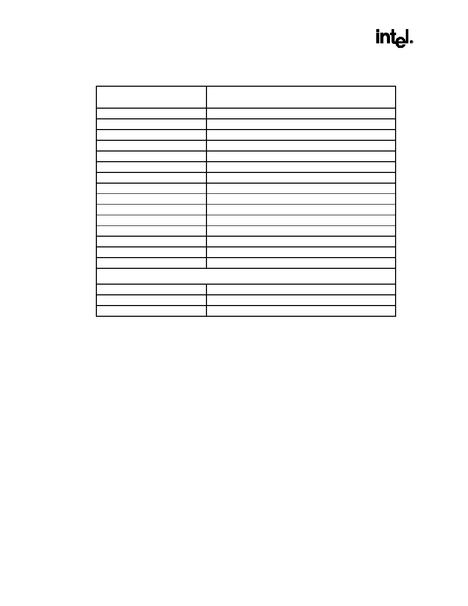
Table 6. Recommended Resistors for Mobile Intel Pentium III Processor-M Signals
Recommended
Resistor Value (
)
Mobile Intel Pentium III Processor-M Signal
1, 2
No pull-up
GHI#
3
10 pull-down
BREQ0#
4
14 pull-up
NCTRL
39 pull-up
TMS
39 pull-down
TCK
56.2 pull-up
PRDY#, RESET#
5
56.2 pull-down
RTTIMPEDP
110 pull-down
EDGECTRLP
150 pull-up
PICD[1:0], TDO
200-300 pull-up
PREQ#, TDI
500 pull-down
TRST#
1K pull-up
BSEL[1:0], TESTHI, VID[4:0], VTTPWRGD
1K pull-down
TESTLO
1.5k pull-up
FERR#, IERR#, PWRGOOD
3K pull-up
FLUSH#
Additional Pullup/Pulldown Resistor Recommendations
7
270 pull-up
SMI#
680 pull-up
STPCLK#
1.5k pull-up
A20M#, DPSLP#, INIT#, IGNNE#, LINT0/INTR, LINT1/NMI
NOTES:
1.
The recommendations above are only for signals that are being used. These recommendations are maximum
values only; stronger pull-ups may be used. Pull-ups for the signals driven by the chipset should not violate the
chipset specification. Refer to Section 3.1.4 for the required pull-up or pull-down resistors for signals that are not
being used.
2.
Open-drain signals must never violate the undershoot specification in Section 4.3. Use stronger pull-ups if there
is too much undershoot.
3.
GHI# has an on-die pull-up to VCCT.
4.
A pull-down on BREQ0# is an alternative to having the central agent to drive BREQ0# low at reset.
5.
A 56.2
1% terminating resistor connected to V
CCT is required.
6.
The following signals are actively driven high by the ICH3-M component and do not need external pull up
resistors on ICH3-M based platforms: A20M#, DPSLP#, INIT#, IGNNE#, LINT0/INTR, LINT1/NMI, SMI#,
STPCLK#.
7.
These pull up recommendations apply to systems on which these signals are not actively pulled high such as
those utilizing the 82443MX chipset.
3.1.1
Power Sequencing Requirements
Unlike the Mobile Pentium III processor, the Mobile Intel Pentium III Processor-M does have specific
power sequencing requirements. The power on sequencing and timings are shown in Figure 12 and
Table 25. Power down timing requirements are shown in Figure 13, Figure 14, and Table 25. The VCC
power plane must not rise too fast. At least 200
sec (TR) must pass from the time that VCC is at 10%
of its nominal value until the time that VCC is at 90% of its nominal value. The recommended VCC rise
and fall times for Enhanced Intel SpeedStep technology and Deeper Sleep transitions are 100
sec
(max). For more details, please refer to the Intel Mobile Voltage Positioning -II (IMVP-II) Design
Guide, which is available from your Intel Field Sales Representative.
相关PDF资料 |
PDF描述 |
|---|---|
| RJ80530GZ933512 | 32-BIT, 933 MHz, MICROPROCESSOR, PBGA479 |
| RJ80536VC001512M | 1000 MHz, MICROPROCESSOR, PBGA479 |
| RJ80536NC0211M | 1500 MHz, MICROPROCESSOR, PBGA479 |
| RK80530KZ006512 | 32-BIT, 1133 MHz, MICROPROCESSOR, CPGA370 |
| RK80530KZ017512 | 32-BIT, 1400 MHz, MICROPROCESSOR, CPGA370 |
相关代理商/技术参数 |
参数描述 |
|---|---|
| RJ80530LY850512 | 制造商:Rochester Electronics LLC 功能描述:- Bulk 制造商:Intel 功能描述: |
| RJ80530LY900512 | 制造商:Rochester Electronics LLC 功能描述:- Bulk |
| RJ80530LZ733512 | 制造商:Rochester Electronics LLC 功能描述:- Bulk |
| RJ80530LZ733512S L5QS | 制造商:Intel 功能描述:MPU Pentium? III Processor 64-Bit 0.13um 733MHz 479-Pin uFCBGA |
| RJ80530LZ866512 | 制造商:Rochester Electronics LLC 功能描述:- Bulk |
发布紧急采购,3分钟左右您将得到回复。