- 您现在的位置:买卖IC网 > PDF目录66140 > RO2053 (RF MONOLITHICS INC) 1-PORT SAW RESONATOR, 310 MHz PDF资料下载
参数资料
| 型号: | RO2053 |
| 厂商: | RF MONOLITHICS INC |
| 元件分类: | SAW谐振器 |
| 英文描述: | 1-PORT SAW RESONATOR, 310 MHz |
| 封装: | ROHS COMPLIANT, HERMETIC, CASE TO39-3, 3 PIN |
| 文件页数: | 2/2页 |
| 文件大小: | 136K |
| 代理商: | RO2053 |
www.RFM.com
E-mail: info@rfm.com
Page 2 of 2
2008 by RF Monolithics, Inc.
RO2053 - 3/25/08
Electrical Connections
This one-port, two-terminal SAW resonator is bidirectional. The terminals
are interchangeable with the exception of circuit board layout.
Typical Test Circuit
The test circuit inductor, LTEST, is tuned to resonate with the static
capacitance, CO at FC.
Typical Application Circuits
Temperature Characteristics
Equivalent LC Model
The following equivalent LC model is valid near resonance:
Case Design
Pin
Connection
1
Terminal 1
2
Terminal 2
3
Case Ground
Network
Analyzer
Network
Analyzer
Electrical Test:
1
2
3
Ω
50
Ω
Source at
F
C
Low-Loss
Matching
Network
50
Ω
to
Power Test:
P
INCIDENT
CW RF Power Dissipation =
-
REFLECTED
P
3
2
1
MPS-H10
+9VDC
47
RF Bypass
L1
C1
C2
200k
Ω
Modulation
Input
ROXXXX
Bottom View
470
Typical Low-Power Transmitter Application:
1
2
3
(Antenna)
+VDC
RF Bypass
L1
C2
ROXXXX
Bottom View
Typical Local Oscillator Application:
1
2
3
Output
+VDC
C1
Dimensions
Millimeters
Inches
Min
Max
Min
Max
A
9.40
0.370
B
3.18
0.125
C
2.50
3.50
0.098
0.138
D
0.46 Nominal
0.018 Nominal
E
5.08 Nominal
0.200 Nominal
F
2.54 Nominal
0.100 Nominal
G
2.54 Nominal
0.100 Nominal
H
1.02
0.040
J1.40
0.055
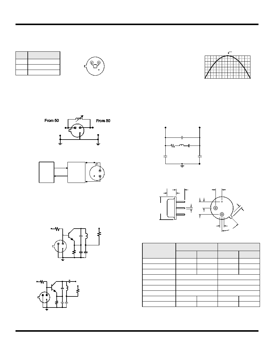
The curve shown on the right
accounts for resonator
contribution only and does not
include oscillator temperature
characteristics.
-80 -60 -40 -20
0 +20 +40 +60
0
-50
-100
-150
+80
-200
0
-50
-100
-150
-200
f
C = f O , T C = T O
ΔT = T
C - T O ( °C )
(f
-f
o
) /
f
(ppm
)
0.5 pF*
0.25 pF*
Cp
Co=
+
*Case Parasitics
R
L
C
0.5 pF*
C p
1
2
3
MM
M
B
45°
J
(2 places)
D
(3 places)
H
G
E
F
C
A
Bottom View
Pin 1
Pin 2
Pin 3
相关PDF资料 |
PDF描述 |
|---|---|
| RO2071-2 | 1-PORT SAW RESONATOR, 980 MHz |
| RO2073A-4 | 1-PORT SAW RESONATOR, 315.05 MHz |
| RO2073A-6 | 1-PORT SAW RESONATOR, 315 MHz |
| RO2101A-15 | 1-PORT SAW RESONATOR, 433.92 MHz |
| RO2101A-17 | 1-PORT SAW RESONATOR, 433.92 MHz |
相关代理商/技术参数 |
参数描述 |
|---|---|
| RO2053A-1 | 制造商:未知厂家 制造商全称:未知厂家 功能描述:Analog IC |
| RO2055 | 制造商:未知厂家 制造商全称:未知厂家 功能描述:Analog IC |
| RO2065 | 制造商:未知厂家 制造商全称:未知厂家 功能描述:Analog IC |
| RO2071 | 制造商:未知厂家 制造商全称:未知厂家 功能描述:Analog IC |
| RO2071-2 | 制造商:RFM 制造商全称:RF Monolithics, Inc 功能描述:980.0 MHz SAW Resonator |
发布紧急采购,3分钟左右您将得到回复。