- 您现在的位置:买卖IC网 > PDF目录67166 > RO3144A-2 (RF MONOLITHICS INC) 1-PORT SAW RESONATOR, 916.5 MHz PDF资料下载
参数资料
| 型号: | RO3144A-2 |
| 厂商: | RF MONOLITHICS INC |
| 元件分类: | SAW谐振器 |
| 英文描述: | 1-PORT SAW RESONATOR, 916.5 MHz |
| 封装: | ROHS COMPLIANT, CERAMIC, CASE SM5035-4 |
| 文件页数: | 1/2页 |
| 文件大小: | 142K |
| 代理商: | RO3144A-2 |
www.RFM.com E-mail: info@rfm.com
Page 1 of 2
2009 by RF Monolithics, Inc.
RO3144A - 7/30/09
Electrical Characteristics
Characteristic
Sym
Notes
Minimum
Typical
Maximum
Units
Frequency, +25 °C
RO3144A
fC
2,3,4,5
916.300
916.700
MHz
RO3144A-1
916.350
916.650
RO3144A-2
916.400
916.600
Tolerance from 916.5 MHz
RO3144A
fC
±200
kHz
RO3144A-1
±150
RO3144A-2
±100
Insertion Loss
IL
2,5,6
1.2
2.5
dB
Quality Factor
Unloaded Q
QU
5,6,7
26500
50
Loaded Q
QL
3000
Temperature Stability
Turnover Temperature
TO
6,7,8
10
25
40
°C
Turnover Frequency
fO
fC
kHz
Frequency Temperature Coefficient
FTC
0.032
ppm/°C2
Frequency Aging
Absolute Value during the First Year
|fA|
1
<±10
ppm/yr
DC Insulation Resistance between Any Two Terminals
5
1.0
M
RF Equivalent RLC Model
Motional Resistance
RM
5, 6, 7, 9
13.1
Motional Inductance
LM
60.3
H
Motional Capacitance
CM
.50
fF
Shunt Static Capacitance
CO
5, 6, 9
2.09
pF
Test Fixture Shunt Inductance
LTEST
2, 7
14.5
nH
Lid Symbolization
RO3144A: 663, RO3144A-1: 897, RO3144A-2: 813, // YWWS
Ideal for 916.5 MHz Transmitters
Very Low Series Resistance
Quartz Stability
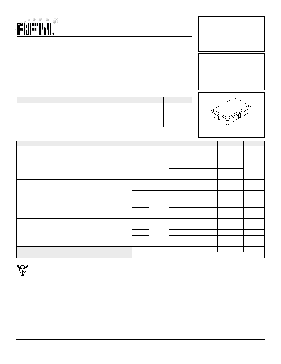
Surface-Mount Ceramic Case with 21 mm2 Footprint
Complies with Directive 2002/95/EC (RoHS)
The RO3144A is a true one-port, surface-acoustic-wave (SAW) resonator in a surface-mount ceramic case.
It provides reliable, fundamental-mode, quartz frequency stabilization of fixed-frequency transmitters
operating at 916.5 MHz.
Absolute Maximum Ratings
Rating
Value
Units
CW RF Power Dissipation
0
dBm
DC Voltage Between Terminals
±30
VDC
Case Temperature
-40 to +85
°C
Soldering Temperature, 10 seconds / 5 cycles maximum
260
°C
916.5 MHz
SAW
Resonator
RO3144A
RO3144A-1
RO3144A-2
CAUTION: Electrostatic Sensitive Device. Observe precautions for handling.
Notes:
1.
Frequency aging is the change in fC with time and is specified at +65°C or
less. Aging may exceed the specification for prolonged temperatures
above +65°C. Typically, aging is greatest the first year after manufacture,
decreasing in subsequent years.
2.
The center frequency, fC, is measured at the minimum insertion loss point,
ILMIN, with the resonator in the 50 test system (VSWR ≤ 1.2:1). The
shunt inductance, LTEST, is tuned for parallel resonance with CO at fC.
Typically, fOSCILLATOR or fTRANSMITTER is approximately equal to the
resonator fC.
3.
One or more of the following United States patents apply: 4,454,488 and
4,616,197.
4.
Typically, equipment utilizing this device requires emissions testing and
government approval, which is the responsibility of the equipment
manufacturer.
5.
Unless noted otherwise, case temperature TC = +25°C±2°C.
6.
The design, manufacturing process, and specifications of this device are
subject to change without notice.
7.
Derived mathematically from one or more of the following directly
measured parameters: fC, IL, 3 dB bandwidth, fC versus TC, and CO.
8.
Turnover temperature, TO, is the temperature of maximum (or turnover)
frequency, fO. The nominal frequency at any case temperature, TC, may be
calculated from: f = fO [1 - FTC (TO -TC)
2]. Typically oscillator T
O is
approximately equal to the specified resonator TO.
9.
This equivalent RLC model approximates resonator performance near the
resonant frequency and is provided for reference only. The capacitance CO
is the static (nonmotional) capacitance between the two terminals
measured at low frequency (10 MHz) with a capacitance meter. The
measurement includes parasitic capacitance with "NC” pads unconnected.
Case parasitic capacitance is approximately 0.05 pF. Transducer parallel
capacitance can by calculated as: CP ≈ CO -0.05pF.
SM5035-4
相关PDF资料 |
PDF描述 |
|---|---|
| RO3144A | 1-PORT SAW RESONATOR, 916.5 MHz |
| RO3144C | 1-PORT SAW RESONATOR, 916.5 MHz |
| RO3144 | 1-PORT SAW RESONATOR, 916.5 MHz |
| RO3164D-1 | 1-PORT SAW RESONATOR, 868.35 MHz |
| RP1053-2 | 2-PORT SAW RESONATOR, 310 MHz |
相关代理商/技术参数 |
参数描述 |
|---|---|
| RO3144C | 功能描述:谐振器 916.5 MHz +/-200kHz Single Port RoHS:否 制造商:Murata 频率:30 MHz 容差:25 PPM 系列:XRCGB 端接类型:SMD/SMT 工作温度范围:- 10 C to + 70 C 尺寸:1.6 mm W x 2 mm L x 0.65 mm H 封装:Reel |
| RO3144C-1 | 功能描述:谐振器 916.5 MHz +/-150kHz Single Port RoHS:否 制造商:Murata 频率:30 MHz 容差:25 PPM 系列:XRCGB 端接类型:SMD/SMT 工作温度范围:- 10 C to + 70 C 尺寸:1.6 mm W x 2 mm L x 0.65 mm H 封装:Reel |
| RO3144C-2 | 功能描述:谐振器 916.5 MHz +/-100kHz Single Port RoHS:否 制造商:Murata 频率:30 MHz 容差:25 PPM 系列:XRCGB 端接类型:SMD/SMT 工作温度范围:- 10 C to + 70 C 尺寸:1.6 mm W x 2 mm L x 0.65 mm H 封装:Reel |
| RO3144D | 功能描述:谐振器 916.5 MHz +/-200kHz Single Port RoHS:否 制造商:Murata 频率:30 MHz 容差:25 PPM 系列:XRCGB 端接类型:SMD/SMT 工作温度范围:- 10 C to + 70 C 尺寸:1.6 mm W x 2 mm L x 0.65 mm H 封装:Reel |
| RO3144D-1 | 功能描述:谐振器 916.5 MHz +/-150kHz Single Port RoHS:否 制造商:Murata 频率:30 MHz 容差:25 PPM 系列:XRCGB 端接类型:SMD/SMT 工作温度范围:- 10 C to + 70 C 尺寸:1.6 mm W x 2 mm L x 0.65 mm H 封装:Reel |
发布紧急采购,3分钟左右您将得到回复。