- 您现在的位置:买卖IC网 > PDF目录67166 > RP1105 (RF MONOLITHICS INC) 2-PORT SAW RESONATOR, 640 MHz PDF资料下载
参数资料
| 型号: | RP1105 |
| 厂商: | RF MONOLITHICS INC |
| 元件分类: | SAW谐振器 |
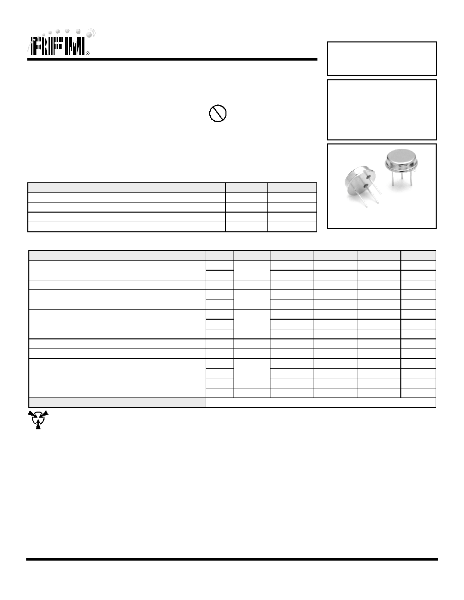
| 英文描述: | 2-PORT SAW RESONATOR, 640 MHz |
| 封装: | ROHS COMPLIANT, HERMETIC, LOW-PROFILE, CASE TO39-3 |
| 文件页数: | 1/2页 |
| 文件大小: | 131K |
| 代理商: | RP1105 |
www.RFM.com E-mail: info@rfm.com
Page 1 of 2
2008 by RF Monolithics, Inc.
RP1105 - 9/11/08
Electrical Characteristics
Characteristic
Sym
Notes
Minimum
Typical
Maximum
Units
Center Frequency
Absolute Frequency
fC
2, 3, 4, 5,
639.900
640.100
MHz
Tolerance from 640.000 MHz
f
C
±100
kHz
Insertion Loss
IL
2, 5, 6
9.1
12.5
dB
Quality Factor
Unloaded Q
QU
5, 6, 7
8,600
50
Loaded Q
QL
5,600
Temperature Stability
Turnover Temperature
TO
6, 7, 8
64
79
94
°C
Turnover Frequency
fO
fC+69
kHz
Frequency Temp. Coefficient
FTC
0.037
ppm/°C2
Frequency Aging
Absolute Value during First Year
|fA|
6
≤ 10
ppm/yr
DC Insulation Resistance between Any Two Pins
5
1.0
M
RF Equivalent RLC
Motional Resistance
RM
5, 7, 9
185
Motional Inductance
LM
395.520
H
Motional Capacitance
CM
0.156356
fF
Shunt Static Capacitance
CO
5, 6, 9
1.7
pF
Lid Symbolization (in addition to Lot and/or Date Codes)
RFM P1105
TO39-3 Case
Ideal for 639.9 or 640.0 MHz Oscillators
Nominal Insertion Phase Shift of 180° at Resonance
Quartz Stability
Rugged, Hermetic, Low-Profile TO39 Case
Complies with Directive 2002/95/EC (RoHS)
The RP1105 is a two-port, 180° surface-acoustic-wave (SAW) resonator in a low-profile TO39 case. It pro-
vides reliable, fundamental-mode, quartz frequency stabilization of fixed-frequency oscillators operating at
or near 640 MHz. In the typical CATV converter second LO application, the nominal LO frequency is
639.90 MHz. For these designs, the nominal resonator frequency is higher than the nominal oscillator fre-
quency to allow for production frequency tuning.
Absolute Maximum Ratings
Rating
Value
Units
CW RF Power Dissipation (See: Typical Test Circuit)
+5
dBm
DC Voltage Between Any Two Pins (Observe ESD Precautions)
±30
VDC
Case Temperature
-40 to +85
°C
Solder Temperature, 10 seconds/5 cycles maximum
260
°C
640.0 MHz
SAW
Resonator
RP1105
CAUTION: Electrostatic Sensitive Device. Observe precautions for handling.
Notes:
1.
Frequency aging is the change in fC with time and is specified at +65°C or less. Aging may exceed the specification for prolonged temperatures
above +65°C. Typically, aging is greatest the first year after manufacture, decreasing significantly in subsequent years.
2.
The frequency fC is the frequency of minimum IL with the resonator in the specified test fixture in a 50 test system with VSWR ≤ 1.2:1. Typically,
fOSCILLATOR or fTRANSMITTER is less than the resonator fC.
3.
One or more of the following United States patents apply: 4,454,488; 4,616,197.
4.
Typically, equipment utilizing this device requires emissions testing and government approval, which is the responsibility of the equipment manufac-
turer.
5.
Unless noted otherwise, case temperature TC = +25°C± 5°C
6.
The design, manufacturing process, and specifications of this device are subject to change without notice.
7.
Derived mathematically from one or more of the following directly measured parameters: fC, IL, 3 dB bandwidth, fC versus TC, and CO.
8.
Turnover temperature, TO, is the temperature of maximum (or turnover) frequency, fO. The nominal frequency at any case temperature, TC, may be
calculated from: f = fO [1 - FTC (TO - TC)
2]. Typically, oscillator T
O is 20° less than the specified resonator TO.
9.
This equivalent RLC model approximates resonator performance near the resonant frequency and is provided for reference only. The capacitance
CO is the measured static (nonmotional) capacitance between either pin 1 and ground or pin 2 and ground. The measurement includes case parasitic
capacitance.
Pb
相关PDF资料 |
PDF描述 |
|---|---|
| RP1261 | 2-PORT SAW RESONATOR, 913.612 MHz |
| RP1234 | 2-PORT SAW RESONATOR, 293.075 MHz |
| RP1053 | 2-PORT SAW RESONATOR, 310 MHz |
| RP1207-5 | 2-PORT SAW RESONATOR, 433.92 MHz |
| RP1316 | 2-PORT SAW RESONATOR, 479.5 MHz |
相关代理商/技术参数 |
参数描述 |
|---|---|
| RP110-6-4.7-QD | 制造商:RADIUS POWER 功能描述:EMI POWER LINE FILTER |
| RP111024 | 制造商:TE Connectivity 功能描述:FLEXLINE |
| RP111060 | 制造商:TE Connectivity 功能描述: |
| RP1110C 110V | 制造商:MAKITA 功能描述:ROUTER 110V 制造商:MAKITA 功能描述:ROUTER, 110V |
| RP111N251B-TR-FE | 制造商:Ricoh 功能描述:Cut Tape |
发布紧急采购,3分钟左右您将得到回复。