- 您现在的位置:买卖IC网 > PDF目录69323 > RX-4571SA 0 TIMER(S), REAL TIME CLOCK, PDSO14 PDF资料下载
参数资料
| 型号: | RX-4571SA |
| 元件分类: | 时钟/数据恢复及定时提取 |
| 英文描述: | 0 TIMER(S), REAL TIME CLOCK, PDSO14 |
| 封装: | ROHS COMPLIANT, SOP-14 |
| 文件页数: | 65/76页 |
| 文件大小: | 1924K |
| 代理商: | RX-4571SA |
第1页第2页第3页第4页第5页第6页第7页第8页第9页第10页第11页第12页第13页第14页第15页第16页第17页第18页第19页第20页第21页第22页第23页第24页第25页第26页第27页第28页第29页第30页第31页第32页第33页第34页第35页第36页第37页第38页第39页第40页第41页第42页第43页第44页第45页第46页第47页第48页第49页第50页第51页第52页第53页第54页第55页第56页第57页第58页第59页第60页第61页第62页第63页第64页当前第65页第66页第67页第68页第69页第70页第71页第72页第73页第74页第75页第76页
USB 2.0 Hi-Speed Hub Controller
Datasheet
Revision 1.1 (04-26-10)
68
SMSC USB251x
DATASHEET
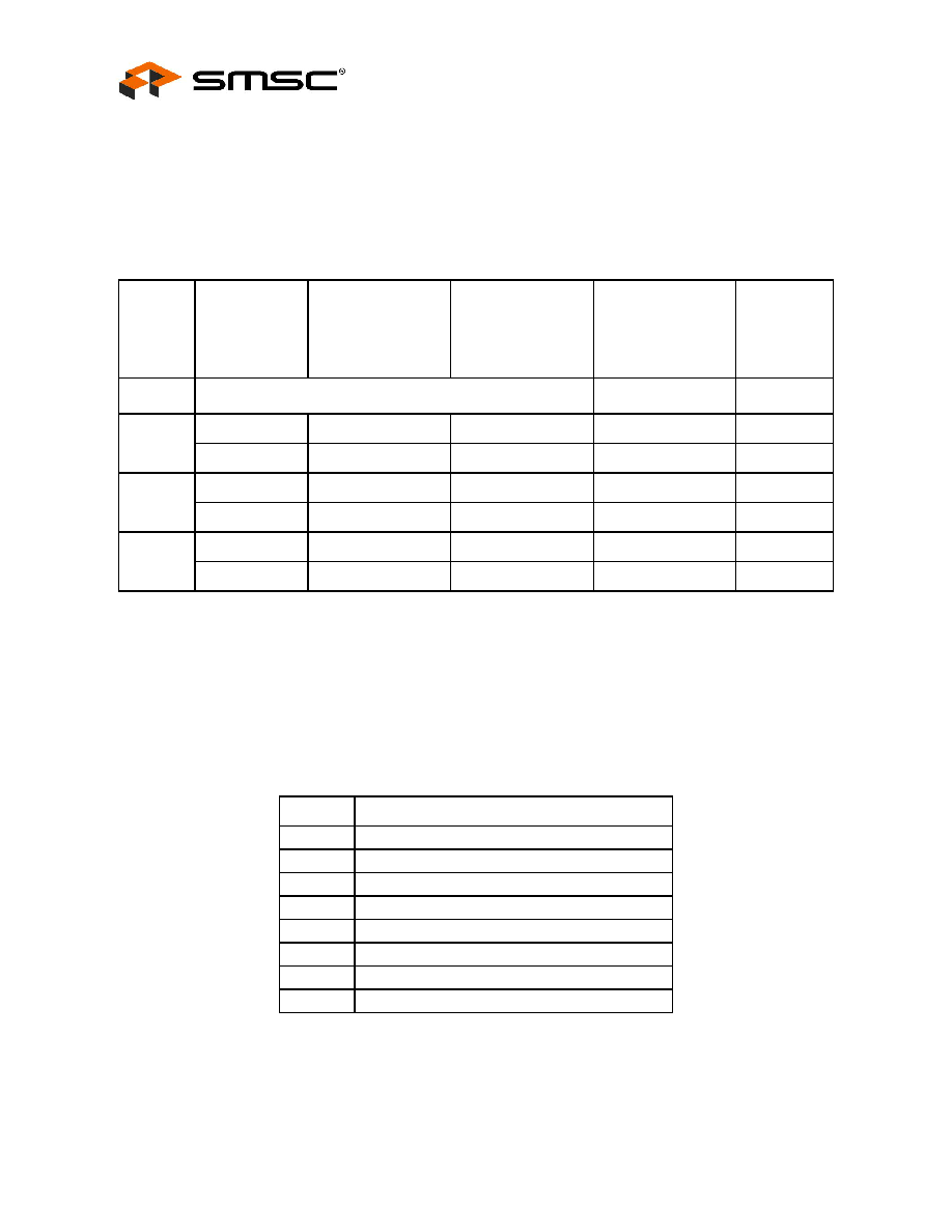
9.2.1
Package Thermal Specifications
Thermal parameters are measured or estimated for devices with the exposed pad soldered to thermal
vias in a multilayer 2S2P PCB per JESD51. Thermal resistance is measured from the die to the
ambient air. The values provided are based on the package body, die size, maximum power
consumption, 85°C ambient temperature, and 125°C junction temperature of the die.
Table 9.12 Package Thermal Resistance Parameters
Use the following formulas to calculate the junction temperature:
TJ = P x ΘJA + TA
TJ = P x ΨJT + TT
TJ = P x ΘJC + TC
Table 9.13 Legend
SYMBOL
USB2512/12i
USB2513/13i
USB2514/14i
(°C/W)
USB2512A/12Ai
(°C/W)
USB2512B/12Bi
USB2513B/13Bi
USB2514B/14Bi
(°C/W)
USB2513/13i
USB2514/14i
(°C/W)
VELOCITY
(meters/sec)
PACKAGE
36-PIN QFN
48-PIN QFN
-
ΘJA
34.2
36.2
40.1
31.6
0
29.9
33.4
35.0
27.6
1
ΨJT
0.3
0.4
0.5
0.3
0
0.5
0.7
0.4
1
ΘJC
3.0
5.1
6.3
3.0
0
3.0
5.1
6.3
3.0
1
SYMBOL
DESCRIPTION
TJ
Junction temperature
P
Power dissipated
ΘJA
Junction-to-ambient-temperature
ΘJC
Junction-to-top-of-package
ΨJT
Junction-to-bottom-of-case
TA
Ambient temperature
TC
Temperature of the bottom of the case
TT
Temperature of the top of the case
相关PDF资料 |
PDF描述 |
|---|---|
| RX-4574SG | 0 TIMER(S), REAL TIME CLOCK, PDSO16 |
| RX-4591CF | 0 TIMER(S), REAL TIME CLOCK, PDSO10 |
| RX-8025NB | 0 TIMER(S), REAL TIME CLOCK, PDSO22 |
| RX-8581JE-3 | REAL TIME CLOCK, PDSO20 |
| RX-8581JE | 0 TIMER(S), REAL TIME CLOCK, PDSO20 |
相关代理商/技术参数 |
参数描述 |
|---|---|
| RX-4571SAB | 制造商:Epson Toyocom Corporation 功能描述:Cut Tape |
| RX-4574LC | 制造商:EPSONTOYOCOM 制造商全称:Epson ToYoCom 功能描述:SERIAL-INTERFACE REAL TIME CLOCK MODULE |
发布紧急采购,3分钟左右您将得到回复。