- 您现在的位置:买卖IC网 > PDF目录299876 > S-8328J25MC-F2F-T2 0.3 A SWITCHING CONTROLLER, 287.5 kHz SWITCHING FREQ-MAX, PDSO5 PDF资料下载
参数资料
| 型号: | S-8328J25MC-F2F-T2 |
| 元件分类: | 稳压器 |
| 英文描述: | 0.3 A SWITCHING CONTROLLER, 287.5 kHz SWITCHING FREQ-MAX, PDSO5 |
| 封装: | PLASTIC, SOT-23, 5 PIN |
| 文件页数: | 7/65页 |
| 文件大小: | 759K |
| 代理商: | S-8328J25MC-F2F-T2 |
第1页第2页第3页第4页第5页第6页当前第7页第8页第9页第10页第11页第12页第13页第14页第15页第16页第17页第18页第19页第20页第21页第22页第23页第24页第25页第26页第27页第28页第29页第30页第31页第32页第33页第34页第35页第36页第37页第38页第39页第40页第41页第42页第43页第44页第45页第46页第47页第48页第49页第50页第51页第52页第53页第54页第55页第56页第57页第58页第59页第60页第61页第62页第63页第64页第65页
SMALL PACKAGE PWM/PFM CONTROL STEP-UP SWITCHING REGULATOR
Rev. 7.2-10
S-8324/8328 Series
Seiko Instruments Inc.
15
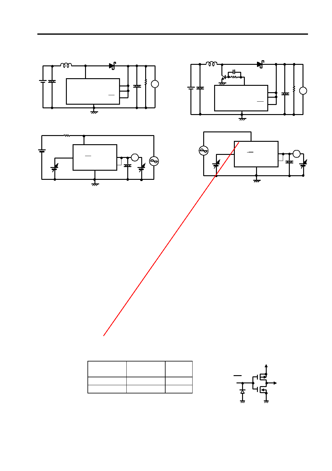
Test Circuits
Operation
1. Step-Up DC/DC Converter
The S-8324/8328 series is a DC/DC converter using a pulse frequency modulation method (PFM) or a pulse width modulation
method (PWM) which are switched automatically according to the load current with a low current consumption.
Especially in the region of 100
A output load current, a high-efficiency DC/DC converter is obtained.
In conventional fixed-duty type PFM DC/DC converters, pulses are skipped at low output load current, causing fluctuation in ripple
frequency of the output voltage, with the result of increase in ripple voltage.
The S-8324/8328 series operates with the PWM control which changes the pulse width duty from 15% to 83%(78% for H, J types)
in the region of large output load current.
The ripple voltage generated from switching can be removed easily through the filter because the switching frequency is constant.
The S-8324/8328 series operates with the PFM control which skips the pulse of the duty 15% pulth width and output that pulse to
the switching transistor according to the load current.
From the above operation, the self current consumption is reduced from the blocking oscilation of the oscilation circuit, and a fall
of efficiency can be protected in small load.
The switching point between PWM and PFM control differs according to the external elements (coil, diode and other), input
voltage and output voltage.
See reference data about this.
Shutdown pin: Stops or starts step-up operation.
(Only for SOT-23-5 package products of A, B, and H Series.)
Turning the shutdown pin low stops operation of all the internal circuits and reduces current consumption
significantly. Do NOT use the shutdown pin in floating state because it has a structure shown in Figure 4 and is
not pulled up or pulled down internally. Do NOT apply voltage of between 0.3 V and 0.75 V to the shutdown pin
because applying such voltage increases the current consumption. If the shutdown pin is not used, connect it to
VOUT (VDD for D, E, J types) pin.
The shutdown pin doesn’t have hysteresis.
Shutdown pin
CR oscillation
circuit
Output
voltage
“H”
Operation
Fixed
“L”
Stop
VIN*
* Voltage obtained by extracting the voltage drop due
to DC resistance of the inductor and the diode
forward voltage from VIN.
1.
VSS
VOUT
CONT
V
-
+
-
+
(ON/OFF)
(VDD)
3.
VSS
VOUT
V
-
+
-
+
(ON/OFF)
Rb
EXT
Cb
(VDD)
Figure 3
Oscilloscope
2.
VSS
(ON/OFF)
VOU
CONT
10 k
-
+
A
(VDD)
4.
Oscilloscope
VSS
(ON/OFF)
VOUT
-
+
A
EXT
(VDD)
ON/OFF
VOUT
(VDD for D, E, J types)
VSS
Figure 4
DISCONTINUED
PRODUCT
相关PDF资料 |
PDF描述 |
|---|---|
| S-8331B20FS-T2G | SWITCHING CONTROLLER, PDSO8 |
| S-8340A25AFT-T2 | 0.1 A SWITCHING CONTROLLER, 690 kHz SWITCHING FREQ-MAX, PDSO8 |
| S-8351A28MC-J2NT2G | SWITCHING REGULATOR, 110 kHz SWITCHING FREQ-MAX, PDSO5 |
| S-93C56ADFJ | 128 X 16 MICROWIRE BUS SERIAL EEPROM, PDSO8 |
| S-93C56BD0I-I8T1G | 128 X 16 MICROWIRE BUS SERIAL EEPROM, PDSO8 |
相关代理商/技术参数 |
参数描述 |
|---|---|
| S832D | 功能描述:SW TOGGLE 3PDT 30A LEVER SCREW RoHS:是 类别:开关 >> 拨动开关 系列:S 标准包装:1 系列:A 电路:双刀双掷 开关功能:开-开-开 触点额定电压:6A @ 125VAC 触动器类型:扁平型 触动器长度:11.38mm 发光:不发光 安装类型:面板安装 端接类型:焊片 轴衬螺纹:1/4-40 包装:散装 |
| S-832D | 制造商:Nihon Kaiheiki Ind Co Ltd 功能描述:250V 50000 Silver 70 -10 42mm 24mm 73mm |
| S832D-RO | 功能描述:拨动开关 3PST ON-NONE-ON RoHS:否 制造商:C&K Components 触点形式:DPDT 开关功能:ON - ON - ON 电流额定值: 电压额定值 AC:20 V 电压额定值 DC:20 V 功率额定值:0.4 VA 端接类型:V-Bracket 安装风格: 端子密封:Epoxy 触点电镀:Gold 照明:Not Illuminated |
| S832-RO | 功能描述:拨动开关 3PDT ON-ON HIGH CAP RoHS:否 制造商:C&K Components 触点形式:DPDT 开关功能:ON - ON - ON 电流额定值: 电压额定值 AC:20 V 电压额定值 DC:20 V 功率额定值:0.4 VA 端接类型:V-Bracket 安装风格: 端子密封:Epoxy 触点电镀:Gold 照明:Not Illuminated |
| S8-32X1 | 制造商:MISCELLANEOUS 功能描述: |
发布紧急采购,3分钟左右您将得到回复。