- 您现在的位置:买卖IC网 > PDF目录192292 > S1M8657X01-E0T0 TELECOM, CELLULAR, BASEBAND CIRCUIT, PQFP48 PDF资料下载
参数资料
| 型号: | S1M8657X01-E0T0 |
| 元件分类: | 无绳电话/电话 |
| 英文描述: | TELECOM, CELLULAR, BASEBAND CIRCUIT, PQFP48 |
| 封装: | 7 X 7 MM, LQFP-48 |
| 文件页数: | 14/34页 |
| 文件大小: | 281K |
| 代理商: | S1M8657X01-E0T0 |
第1页第2页第3页第4页第5页第6页第7页第8页第9页第10页第11页第12页第13页当前第14页第15页第16页第17页第18页第19页第20页第21页第22页第23页第24页第25页第26页第27页第28页第29页第30页第31页第32页第33页第34页
TX IF/BBA WITH AGC
S1M8657
21
The M in binary can be set by changing the PLLR1[7:5] register value. And normally, f
ERROR is designed to the
limit of 1kHz.
[An example of a Lock length design ]
fVCO = 260.76MHz; fTCXO = 19.68MHz; fERROR = 1kHz; R = 16, N = 212
fR = fTCXO/R = 19.68MHz/16 = 1.23MHz
fv = (fVCO + fERROR)/N = 1230004.71698
NPD = 2
× TTCXO/(1/fR - 1/fv) = 32600
NTCXO = R
× NPD = 16 × 32600 = 521600
M = Roundup{log2(NTCXO)} - 13 = Roundup(18.9926) - 13 = 6
Therefore. Lock detector length is 2
19 TCXO.
General Purpose ADC
The GP-ADC for the system monitor has a built-in 3-input switch Serial 8-BIT A-D Converter and is used
generally used to sense the temperature, and battery amount and type. The GP-ADC can be controlled by the
following methods.
Parallel control as in the existing S1M8653B when the SPI is not used and SEN = low.
GPENA, GPDATA, and GPCLK must be used.
Basic and enhanced modes exist with SPI use when SEN = High
: Controlled through the SPI register and GPENA in the Basic Mode(TXMODE_CONT[0] = Low),
and can output through either the SPI register or GPDATA and GPCLK pins.
: Controlled according to the contents in the GPADC_MODE[7:0] in the Enhanced
Mode(TXMODE_CONT[0] = High).
General Purpose ADC Operation without SPI (SEN = low)
When SEN = low, the Serial BUS(SPI BUS) is not used. In such a case, GP-ADC is controlled through SLSB,
SMSB, GPENA, GPDATA and GPCLK provided from external pins or data must be sent. Under these
conditions, the GP-ADC is reset at the rising edge of GPENA from the modem and starts the conversion. The
converted digital code is synchronized to the continuous 9 GPCLK and sent to the modem. To start a new GP-
ADC conversion, GPENA must be at Low. Input range or signal are selected based on the SMSB/PAON and
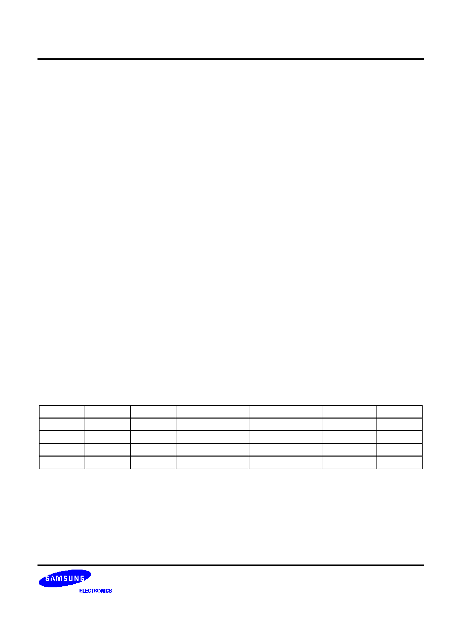
SLSB/CLK states, as shown in Table 2.
Table 2. Input and Range Select (SEN = low)
SMSB
SLSB
GPIN
Vin MID
Input Range
LSB/Step
Zin
0
GPIN1
0.75V
0.5V
2mV
∞
0
1
GPIN1
1.5V
2V
8mV
∞
1
0
GPIN2
1.5V
2V
8mV
∞
1
GPIN3
1.5V
2V
8mV
∞
相关PDF资料 |
PDF描述 |
|---|---|
| S1M8657X01-F0T0 | TELECOM, CELLULAR, BASEBAND CIRCUIT, BCC48 |
| S1M8660AX01-F0T0 | SPECIALTY TELECOM CIRCUIT, CBCC48 |
| S1M8836X01-G0T0 | PLL FREQUENCY SYNTHESIZER, 1000 MHz, CQCC24 |
| S1P-SLV | 1 CONTACT(S), FEMALE, TWO PART BOARD CONNECTOR, CRIMP |
| S1T0567X01-D0B0 | TELECOM, TONE DECODER CIRCUIT, PDIP8 |
相关代理商/技术参数 |
参数描述 |
|---|---|
| S1M8657X01-F0T0 | 制造商:SAMSUNG 制造商全称:Samsung semiconductor 功能描述:TX IF/BBA WITH AGC |
| S1M8660A | 制造商:SAMSUNG 制造商全称:Samsung semiconductor 功能描述:RX IF / BBA WITH GPS |
| S1M8660AX01-F0T0 | 制造商:SAMSUNG 制造商全称:Samsung semiconductor 功能描述:RX IF / BBA WITH GPS |
| S1M8662A | 制造商:SAMSUNG 制造商全称:Samsung semiconductor 功能描述:CDMA/PCS/GPS Triple Mode IF/ baseband IC |
| S1M8662AX01-F0T0 | 制造商:SAMSUNG 制造商全称:Samsung semiconductor 功能描述:CDMA/PCS/GPS Triple Mode IF/ baseband IC |
发布紧急采购,3分钟左右您将得到回复。