- 您现在的位置:买卖IC网 > PDF目录85237 > S201S06V (SHARP ELECTRONICS CORP) TRIGGER OUTPUT SOLID STATE RELAY, 3000 V ISOLATION-MAX PDF资料下载
参数资料
| 型号: | S201S06V |
| 厂商: | SHARP ELECTRONICS CORP |
| 元件分类: | 继电器,输入/输出模块 |
| 英文描述: | TRIGGER OUTPUT SOLID STATE RELAY, 3000 V ISOLATION-MAX |
| 封装: | PLASTIC, SIP-4 |
| 文件页数: | 12/13页 |
| 文件大小: | 239K |
| 代理商: | S201S06V |
8
S101S06V Series
S201S06V Series
■ Design Considerations
In order for the SSR to turn off, the triggering current (lF) must be 0.1mA or less.
When the input current (IF) is below 0.1mA, the output Triac will be in the open circuit mode. However, if the
voltage across the Triac, VD, increases faster than rated dV/dt, the Triac may turn on. To avoid this situation,
please incorporate a snubber circuit. Due to the many different types of load that can be driven, we can
merely recommend some circuit vales to start with : Cs=0.022F and Rs=47. The operation of the SSR
and snubber circuit should be tested and if unintentional switching occurs, please adjust the snubber circuit
component values accordingly.
When making the transition from On to Off state, a snubber circuit should be used ensure that sudden drops
in current are not accompanied by large instantaneous changes in voltage across the Triac.
This fast change in voltage is brought about by the phase difference between current and voltage.
Primarily, this is experienced in driving loads which are inductive such as motors and solenoids.
Following the procedure outlined above should provide sufficient results.
For over voltage protection, a Varistor may be used.
Any snubber or Varistor used for the above mentioned scenarios should be located as close to the main out-
put triac as possible.
Particular attention needs to be paid when utilizing SSRs that incorporate zero crossing circuitry.
If the phase difference between the voltage and the current at the output pins is large enough, zero crossing
type SSRs cannot be used. The result, if zero crossing SSRs are used under this condition, is that the SSR
may not turn on and off irregardless of the input current. In this case, only a non zero cross type SSR should
be used in combination with the above mentioned snubber circuit selection process.
The load current should be within the bounds of derating curve. (Refer to Fig.2)
Also, please use the optional heat sink when necessary.
In case the optional heat sink is used and the isolation voltage between the device and the optional heat sink
is needed, please locate the insulation sheet between the device and the heat sink.
When the optional heat sink is equipped, please set up the M3 screw-fastening torque at 0.3 to 0.5Nm.
In order to dissipate the heat generated from the inside of device effectively, please follow the below sugges-
tions.
● Design guide
Sheet No.: D4-A02201EN
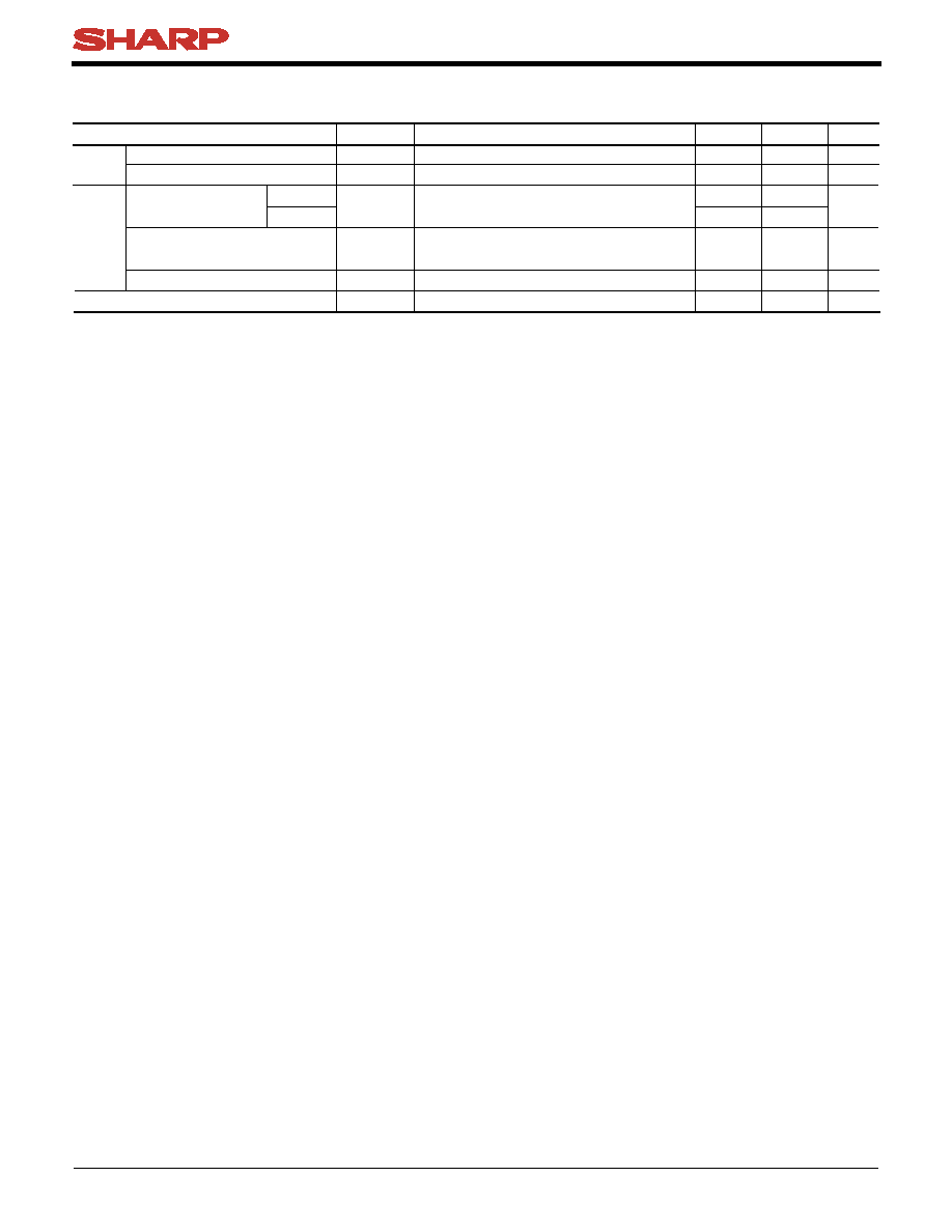
● Recommended Operating Conditions
Parameter
S101S06V
S201S06V
Symbol
Unit
Input
Output
Input signal current at ON state
Input signal current at OFF state
Load supply voltage
Load supply current
Frequency
Operating temperature
IF(ON)
IF(OFF)
VOUT(rms)
IOUT(rms)
f
Topr
mA
V
mA
Hz
C
Locate snubber circuit between output terminals
(Cs
=0.022F, Rs=47)
Conditions
() See Fig.2 about derating curve (IT(rms) vs. ambient temperature).
25
0
80
0.1
47
20
35
0.1
120
240
IT(rms)
×80%()
63
80
MIN.
MAX.
相关PDF资料 |
PDF描述 |
|---|---|
| SFH4259-U | 2.575 mm, 1 ELEMENT, INFRARED LED, 850 nm |
| SSF-LXHM107USBD | T-1 SINGLE COLOR LED, ULTRA SUPER BLUE, 3 mm |
| SDS60R2K | TRANSISTOR OUTPUT SOLID STATE RELAY, 2500 V ISOLATION-MAX |
| SR75-2W | TRANSISTOR OUTPUT SOLID STATE RELAY, 1000 V ISOLATION-MAX |
| SEL1420G | SINGLE COLOR LED, GREEN, 5 mm |
相关代理商/技术参数 |
参数描述 |
|---|---|
| S201S15V | 制造商:SHARP 制造商全称:Sharp Electrionic Components 功能描述:SIP Type SSR with Built-in Snubber Circuit |
| S201S16V | 制造商:SHARP 制造商全称:Sharp Electrionic Components 功能描述:SIP Type SSR with Built-in Snubber Circuit |
| S201TL | 功能描述:电容套件 TUNING CAP KIT 0.2pF-1000pF 50pcs RoHS:否 制造商:Nichicon 电容范围:10 uF to 680 uF 公差范围: 电压范围:6.3 V to 25 V 产品:Aluminum Organic Polymer Capacitor Kit |
| S201TS | 制造商:JOHANSON 制造商全称:Johanson Technology Inc. 功能描述:RF Ceramic Component Proto-Typing Kits |
| S201U-K1 | 制造商:ABB Low Voltage Products and Systems 功能描述:Circuit Breaker, Branch Circ. Protection, K Curve, 1-P, 1A, 10kA, 240VAC, UL489 |
发布紧急采购,3分钟左右您将得到回复。