- 您现在的位置:买卖IC网 > PDF目录368612 > S5K437CA (SAMSUNG SEMICONDUCTOR CO. LTD.) 1/4 Optical Size 640x480 (VGA) 2.8V CMOS Image Sensor PDF资料下载
参数资料
| 型号: | S5K437CA |
| 厂商: | SAMSUNG SEMICONDUCTOR CO. LTD. |
| 英文描述: | 1/4 Optical Size 640x480 (VGA) 2.8V CMOS Image Sensor |
| 中文描述: | 1 / 4光学尺寸640 × 480(VGA)的2.8V的CMOS图像传感器 |
| 文件页数: | 27/36页 |
| 文件大小: | 285K |
| 代理商: | S5K437CA |
第1页第2页第3页第4页第5页第6页第7页第8页第9页第10页第11页第12页第13页第14页第15页第16页第17页第18页第19页第20页第21页第22页第23页第24页第25页第26页当前第27页第28页第29页第30页第31页第32页第33页第34页第35页第36页
1/4 INCH VGA CMOS IMAGE SENSOR
S5K437CX
23
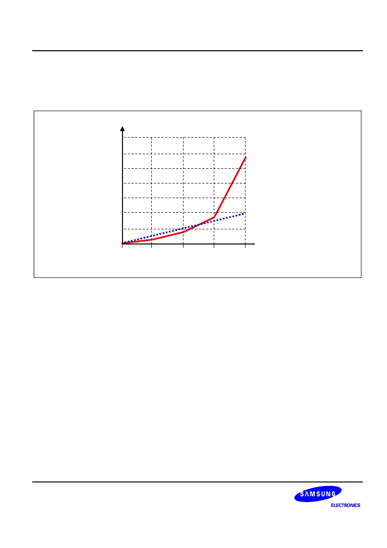
By appropriately programming these four register values, you can acquire different output resolutions depending
on the signal and can increase the intra-scene dynamic range by 16 times. In another application, the sectional
global gain control can be used as a rough gamma correction with four sectional linear approximation curves as
shown in Figure 9.
255
0
511
767
1023
ADC output code at 10-bit resolution
sgg1=1111b
sgg3=0011b
sgg2=0111b
sgg4=0000b
A
sgg1=0111b
sgg2=0111b
sgg3=0111b
sgg4=0111b
sgg1
sgg2
sgg3
sgg4
Figure 9. Quadrisectional Global Gain Control
3. Post Processing
3-1. Auto Dark Level Compensation(ADLC)
The dark level of Image sensor means the average output level without illumination. It includes pixel output
caused by leakage current of the photodiodes and ADC offset. To compensate the dark level, the output level of
optical black(OB) pixels should be in a good reference value. Auto Dark Level Compensation has 4 operating
modes. ADLC mode A only works for (adlc_length +1) frame time. ADLC mode B only works when the change of
shutter values is detected at the start of each frame. ADLC mode C only works when the change of channel gain
values is detected at the start of each frame. ADLC mode D works always when this register is set to high. When
ADLC mode is activated, the image sensor detects the OB pixel level, optionally 512X2 or 128X8, at the start of
the enabled frame, and analog-to-digital conversion range is shifted to compensate the dark level for that frame.
So, the resulting output data of that frame will be almost zero under dark state. You can select the dark level
which is not zero on the ADC Offset Register (adcoffs). The lower 7-bit value represents the offset value in output
code for compensation and the MSB shows whether the offset is positive (adcoffs[7]=0) or negative
(adcoffs[7]=1). When not in auto dark level compensation mode, the adcoffs[7:0] act as a output code value to
subtract the output image data. Please note that all the 8-bit data are used for an offset value without a sign bit.
The resulting ADLC value is expressed as;
ADLC
current
=
α
* (OB
old
+ OB
new
) +
β
* ADLC
old
(
α
is set by register feedback_gain_A ,
β
is set by register feedback_gain_B)
相关PDF资料 |
PDF描述 |
|---|---|
| S5K437CX01 | 1/4 Optical Size 640x480 (VGA) 2.8V CMOS Image Sensor |
| S5K437CX02 | 1/4 Optical Size 640x480 (VGA) 2.8V CMOS Image Sensor |
| S5K437CX03 | 1/4 Optical Size 640x480 (VGA) 2.8V CMOS Image Sensor |
| S5L1462B01-Q0R0 | CD and DVD playback |
| S5L1462B | CD and DVD playback |
相关代理商/技术参数 |
参数描述 |
|---|---|
| S5K437CX01 | 制造商:SAMSUNG 制造商全称:Samsung semiconductor 功能描述:1/4 Optical Size 640x480 (VGA) 2.8V CMOS Image Sensor |
| S5K437CX02 | 制造商:SAMSUNG 制造商全称:Samsung semiconductor 功能描述:1/4 Optical Size 640x480 (VGA) 2.8V CMOS Image Sensor |
| S5K437CX03 | 制造商:SAMSUNG 制造商全称:Samsung semiconductor 功能描述:1/4 Optical Size 640x480 (VGA) 2.8V CMOS Image Sensor |
| S5K711CA | 制造商:SAMSUNG 制造商全称:Samsung semiconductor 功能描述:1/7 CIF CMOS Image Sensor |
| S5K711CA01 | 制造商:SAMSUNG 制造商全称:Samsung semiconductor 功能描述:1/7 CIF CMOS Image Sensor |
发布紧急采购,3分钟左右您将得到回复。