- 您现在的位置:买卖IC网 > PDF目录299880 > S7C38SS-10.0000 (PERICOM SEMICONDUCTOR CORP) TCXO, CLIPPED SINE OUTPUT, 10 MHz PDF资料下载
参数资料
| 型号: | S7C38SS-10.0000 |
| 厂商: | PERICOM SEMICONDUCTOR CORP |
| 元件分类: | XO, clock |
| 英文描述: | TCXO, CLIPPED SINE OUTPUT, 10 MHz |
| 封装: | CERAMIC, SMD, 8 PIN |
| 文件页数: | 1/2页 |
| 文件大小: | 525K |
| 代理商: | S7C38SS-10.0000 |
SaRonix
Technical Data
DS-241
REV 02
S6C & S7C Series
TCXO (optional Voltage Control) 3 or 3.3V, Ceramic SMD
ADV
ANCE
INFORMA
TION
Frequency Range:
Frequency Stability:
vs. temperature: ±1ppm to ±5ppm, as specified
vs. supply voltage (±5% change): ±0.3 ppm
vs. aging: ±1ppm @40°C for one year
vs. load: ±0.3 ppm, (CL: 10pF ±10%)
vs. hysteresis: ±0.2ppm (
δΤ/δt = 1°C/min)
vs. temp. cycles: ±0.2ppm (10 cycles min-max storage temp.)
vs. reflow: ±1.5ppm max (room temp., nominal VC, first reflow)
Perturbations: 0.3ppm peak-to-peak max
10 MHz to 30 MHz
Description
A surface mountable, temperature com-
pensated crystal oscillator with voltage
control option for 3 or 3.3 Volt opera-
tion. The miniature size, extremely low
profile and low power consumption of
this (V)TCXO make it ideally suited for
compact or portable wireless/microwave
networking and telecommunications. The
hermetically sealed ceramic package is
fully compatible with standard surface
mounting processes.
ACTUAL SIZE
Temperature Range:
Operating:
Storage:
0 to +55°C, -20 to +75°C, -40 to +85°C, or as specified
-40 to +85°C
Applications & Features
GPS/Navigation
Mobile and Portable Radio/Telephone
Communications Transceivers
Commercial SATCOM
Microwave transceivers
Wireless networking/Digital datalinks
3 or 3.3 Volt operation
Analog compensation for superb phase
noise and tight stabilities
Miniature 5 x 7 mm, very low profile
2.0mm max height package
Optional voltage control pin for
frequency tuning
Advanced lead-free design and
manufacturing techniques
Available on tape & reel; 16mm tape,
500pcs per reel
Supply Voltage:
3.0V ±5% or 3.3V ±5%
Supply Current:
2mA max (3V); 2.25mA max (3.3V)
1.0V peak-to-peak min
10K
// 10pF
Output:
Clipped Sinewave
Pull Characteristics
(if applicable):
Mechanical:
Shock:
Solderability:
Vibration:
Solvent Resistance:
Resistance to Soldering Heat:
Terminal Strength:
MIL-STD-883, Method 2002, Condition B
MIL-STD-883, Method 2003
MIL-STD-883, Method 2007, Condition A
MIL-STD-202, Method 215
MIL-STD-202, Method 210, Condition I or J
MIL-STD-883, Method 2004, Condition D
Environmental:
Gross Leak Test:
Fine Leak Test:
Thermal Shock:
Moisture Resistance:
MIL-STD-883, Method 1014, Condition C
MIL-STD-883, Method 1014, Condition A2
MIL-STD-883, Method 1011, Condition A
MIL-STD-883C, Method 1004
SaRonix
www.pericom.com/saronix
Level:
Load:
Rated Control Voltage (VC):
Relative Pull Range (VC = 1.5V ±1V):
Input Impedance (pin 1):
Transfer Function:
0.5V to 2.5V
±5ppm to ±12ppm (see part number guide)
1M
min, 2M typ
Frequency increases when control voltage increases
-40 dBc/Hz @ 1Hz
-80 dBc/Hz @ 10Hz
-110 dBc/Hz @ 100Hz
-135 dBc/Hz @ 1kHz
-140 dBc/Hz @ 10kHz
-145 dBc/Hz @ 100kHz
Phase Noise:
(offset from carrier)
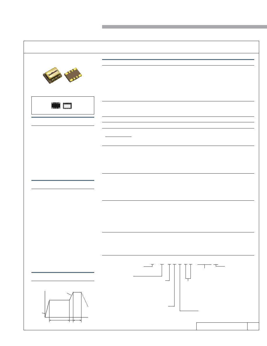
Solder Reflow Guide
Preheat 150 ±10°C
4°C/sec
max
Temperature
–
°C
8°C/sec max
1.5 ~ 2 minutes
10 sec max
Time
150
200
250
Reflow 250°C max
Cooling
1
to
5°C/sec
Part Numbering Guide
S C
5
8 S S V B – 10.0000 (T)
Packaging
Blank = Bulk
(T) = Tape & Reel*
*full reel increments
only (500pcs)
Nominal
Frequency, MHz
Model
6 = 3V
7 = 3.3V
Temperature Stability
3 = ±1.0ppm max
4 = ±1.5ppm max
5 = ±2.0ppm max
6 = ±2.5ppm max
7 = ±3.0ppm max
C = ±3.5ppm max
A = ±4.0ppm max
8 = ±5.0ppm max
Operating Temperature
1 =
0 to +55°C
8 = -10 to +60°C
4 = -20 to +75°C
9 = -30 to +80°C
7 = -40 to +85°C
Package Type
S = Surface Mount
5 x 7mm ceramic
Output
S = Clipped Sinewave
Relative Pulling Range
Blank = TCXO, No Control Voltage
VA = ±5ppm min
VB = ±8ppm min
VC = ±10ppm min
VD = ±12ppm min
Please inquire about availability for specific Operating Temperatures
Please inquire about availability for specific Temperature Stabilities
相关PDF资料 |
PDF描述 |
|---|---|
| S6C58SS-FREQ | TCXO, CLIPPED SINE OUTPUT, 10 MHz - 30 MHz |
| S6C68SS-10.0000(T) | TCXO, CLIPPED SINE OUTPUT, 10 MHz |
| S7C71SS-10.0000(T) | TCXO, CLIPPED SINE OUTPUT, 10 MHz |
| S6CC7SS-FREQ | TCXO, CLIPPED SINE OUTPUT, 10 MHz - 30 MHz |
| S6CC8SS-FREQ | TCXO, CLIPPED SINE OUTPUT, 10 MHz - 30 MHz |
相关代理商/技术参数 |
参数描述 |
|---|---|
| S7CA-08S12L | 制造商:Bel Fuse 功能描述:DC/DC PS SGL-OUT 12V 8.5A 100W - Trays 制造商:Bel Fuse 功能描述:Module DC-DC 1-OUT 12V 8.5A 100W 5-Pin 1/16-Brick |
| S7CA-08S12LG | 制造商:Bel Fuse 功能描述:DC/DC PS SGL-OUT 12V 8.5A 100W 5PIN 1/16-BRICK - Trays 制造商:Bel Fuse 功能描述:Module DC-DC 1-OUT 12V 8.5A 100W 5-Pin 1/16-Brick Tray |
| S7DB-04C500 | 制造商:Bel Fuse 功能描述:DC/DC PS SGL-OUT 5V 4A 20W 12PDIP SMD - Trays |
| S7DB-04C500G | 制造商:Bel Fuse 功能描述:Module DC-DC 1-OUT 5V 4A 20W 12-Pin DIP SMD Tray |
| S7DB-04HX20 | 制造商:Bel Fuse 功能描述:Module DC-DC 1-OUT 10V to 12V 3.5A 42W 12-Pin PDIP SMD |
发布紧急采购,3分钟左右您将得到回复。