- 您现在的位置:买卖IC网 > PDF目录40046 > SA6.0ALF (ON SEMICONDUCTOR) 500 W, UNIDIRECTIONAL, SILICON, TVS DIODE PDF资料下载
参数资料
| 型号: | SA6.0ALF |
| 厂商: | ON SEMICONDUCTOR |
| 元件分类: | TVS二极管 - 瞬态电压抑制 |
| 英文描述: | 500 W, UNIDIRECTIONAL, SILICON, TVS DIODE |
| 封装: | PLASTIC, CASE 59, 2 PIN |
| 文件页数: | 2/5页 |
| 文件大小: | 58K |
| 代理商: | SA6.0ALF |
SA5.0A Series
http://onsemi.com
254
ELECTRICAL CHARACTERISTICS (TA = 25°C unless
otherwise noted, VF = 3.5 V Max. @ IF (Note 6) = 35 A)
Symbol
Parameter
IPP
Maximum Reverse Peak Pulse Current
VC
Clamping Voltage @ IPP
VRWM
Working Peak Reverse Voltage
IR
Maximum Reverse Leakage Current @ VRWM
VBR
Breakdown Voltage @ IT
IT
Test Current
QVBR
Maximum Temperature Variation of VBR
IF
Forward Current
VF
Forward Voltage @ IF
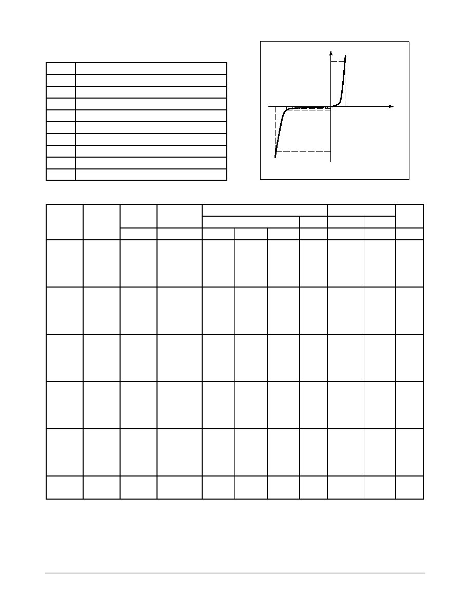
UniDirectional TVS
IPP
IF
V
I
IR
IT
VRWM
VC VBR
VF
ELECTRICAL CHARACTERISTICS (TA = 25°C unless otherwise noted, VF = 3.5 V Max. @ IF (Note 6) = 35 A)
Breakdown Voltage
VC @ IPP (Note 5)
VRWM
(Note 3)
IR @ VRWM
VBR (Note 4) (Volts)
@ IT
VC
IPP
QVBR
Device
Marking
Volts
mA
Min
Nom
Max
mA
Volts
A
mV/
°C
SA5.0A
5
600
6.4
6.7
7
10
9.2
54.3
5
SA6.0A
6
600
6.67
7.02
7.37
10
10.3
48.5
5
SA7.0A
7
150
7.78
8.19
8.6
10
12
41.7
6
SA7.5A
7.5
50
8.33
8.77
9.21
1
12.9
38.8
7
SA8.0A*
8
25
8.89
9.36
9.83
1
13.6
36.7
7
SA8.5A
8.5
5
9.44
9.92
10.4
1
14.4
34.7
8
SA9.0A
9
1
10
10.55
11.1
1
15.4
32.5
9
SA10A
10
1
11.1
11.7
12.3
1
17
29.4
10
SA11A
11
1
12.2
12.85
13.5
1
18.2
27.4
11
SA12A
12
1
13.3
14
14.7
1
19.9
25.1
12
SA13A
13
1
14.4
15.15
15.9
1
21.5
23.2
13
SA14A
14
1
15.6
16.4
17.2
1
23.2
21.5
14
SA15A
15
1
16.7
17.6
18.5
1
24.4
20.6
16
SA16A
16
1
17.8
18.75
19.7
1
26
19.2
17
SA17A
17
1
18.9
19.9
20.9
1
27.6
18.1
19
SA18A
18
1
20
21.05
22.1
1
29.2
17.2
20
SA20A
20
1
22.2
23.35
24.5
1
32.4
15.4
23
SA22A
22
1
24.4
25.65
26.9
1
35.5
14.1
25
SA24A
24
1
26.7
28.1
29.5
1
38.9
12.8
28
SA26A
26
1
28.9
30.4
31.9
1
42.1
11.9
30
SA28A
28
1
31.1
32.75
34.4
1
45.4
11
31
SA30A
30
1
33.3
35.05
36.8
1
48.4
10.3
36
NOTE:
Devices listed in bold, italic are ON Semiconductor Preferred devices. Preferred devices are recommended choices for
future use and best overall value.
3. MiniMOSORB
transients suppressor is normally selected according to the maximum working peak reverse voltage (VRWM), which
should be equal to or greater than the dc or continuous peak operating voltage level.
4. VBR measured at pulse test current IT at an ambient temperature of 25°C.
5. Surge current waveform per Figure 4 and derate per Figures 1 and 2.
6. 1/2 sine wave (or equivalent square wave), PW = 8.3 ms, duty cycle = 4 pulses per minute
*Not Available in the 5000/Tape & Reel.
相关PDF资料 |
PDF描述 |
|---|---|
| SA130ALF | 500 W, UNIDIRECTIONAL, SILICON, TVS DIODE |
| SA100ATR | 500 W, UNIDIRECTIONAL, SILICON, TVS DIODE |
| SA100CTR | 500 W, BIDIRECTIONAL, SILICON, TVS DIODE |
| SA10CTR | 500 W, BIDIRECTIONAL, SILICON, TVS DIODE |
| SA120ATR | 500 W, UNIDIRECTIONAL, SILICON, TVS DIODE |
相关代理商/技术参数 |
参数描述 |
|---|---|
| SA60ARL | 制造商:ONSEMI 制造商全称:ON Semiconductor 功能描述:500 Watt Peak Power MiniMOSORB Zener Transient Voltage Suppressors |
| SA60A-T3 | 制造商:WTE 制造商全称:Won-Top Electronics 功能描述:500W TRANSIENT VOLTAGE SUPPRESSOR |
| SA60A-T8 | 制造商:WTE 制造商全称:Won-Top Electronics 功能描述:500W TRANSIENT VOLTAGE SUPPRESSOR |
| SA60A-TP | 制造商:Micro Commercial Components (MCC) 功能描述:Diode TVS Single Uni-Dir 60V 500W 2-Pin DO-15 T/R |
| SA60ATR | 制造商:World Products 功能描述: |
发布紧急采购,3分钟左右您将得到回复。