- 您现在的位置:买卖IC网 > PDF目录54461 > SB130 (GENERAL SEMICONDUCTOR INC) 1 A, 30 V, SILICON, SIGNAL DIODE, DO-204AL PDF资料下载
参数资料
| 型号: | SB130 |
| 厂商: | GENERAL SEMICONDUCTOR INC |
| 元件分类: | 二极管(射频、小信号、开关、功率) |
| 英文描述: | 1 A, 30 V, SILICON, SIGNAL DIODE, DO-204AL |
| 封装: | PLASTIC, DO-41, 2 PIN |
| 文件页数: | 1/2页 |
| 文件大小: | 38K |
| 代理商: | SB130 |
SB120 thru SB160
Schottky Barrier Rectifier
Reverse Voltage 20 to 60V
Forward Current 1.0A
Maximum Ratings and Thermal Characteristics (TA = 25°C unless otherwise noted)
Parameter
Symbol
SB120
SB130
SB140
SB150
SB160
Unit
Maximum repetitive peak reverse voltage
VRRM
20
30
40
50
60
V
Maximum RMS voltage
VRMS
14
21
28
35
42
V
Maximum DC blocking voltage
VDC
20
30
40
50
60
V
Maximum average forward rectified current
IF(AV)
1.0
A
at 0.375” (9.5mm) lead length (See Fig. 1)
Peak forward surge current 8.3ms single half sine-wave
IFSM
40
A
superimposed on rated load (JEDEC Method)
Typical thermal resistance (1)
R
θJA
50
R
θJL
15
°C/W
Operating junction temperature range
TJ
–65 to +125
–65 to +150
°C
Storage temperature range
TSTG
–65 to +150
°C
Electrical Characteristics (TA = 25°C unless otherwise noted)
Maximum instantaneous
VF
0.50
0.70
V
forward voltage at 1.0A (2)
Maximum instantaneous reverse current
TA = 25°C
IR
0.5
mA
at rated DC blocking voltage (2)
TA = 100°C
10
5.0
Notes: (1) Thermal resistance junction to lead P.C.B. mounted 0.375” (9.5mm) lead length
(2) Pulse test: 300
s pulse width, 1% duty cycle
Features
Plastic package has Underwriters Laboratory
Flammability Classification 94V-0
Low power loss, high efficiency
For use in low voltage high frequency inverters,
free wheeling, and polarity protection applications
Guardring for overvoltage protection
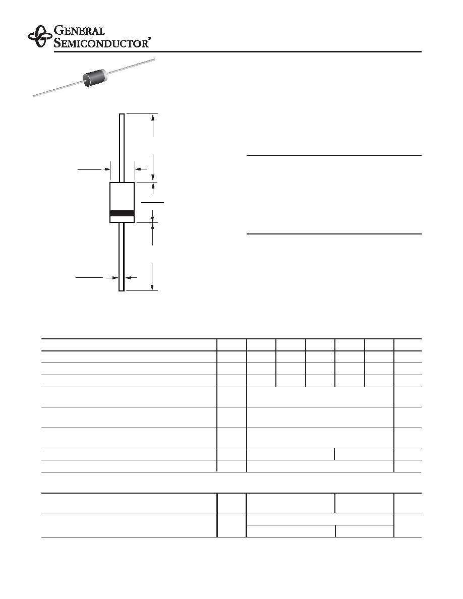
Mechanical Data
Case: JEDEC DO-204AL molded plastic body
Terminals: Plated axial leads, solderable per
MIL-STD-750, Method 2026
High temperature soldering guaranteed:
250°C/10 seconds 0.375” (9.5mm) lead length,
5lbs. (2.3kg) tension
Polarity: Color band denotes cathode end
Mounting Position: Any
Weight: 0.012 ounce, 0.34 gram
0.107 (2.7)
0.080 (2.0)
0.034 (0.86)
0.028 (0.71)
DIA.
1.0 (25.4)
MIN.
1.0 (25.4)
MIN.
0.205 (5.2)
0.160 (4.1)
DIA.
Dimensions in inches
and (millimeters)
DO-204AL (DO-41)
10/3/01
Dimensions in inches and (millimeters)
相关PDF资料 |
PDF描述 |
|---|---|
| SB1530-AP | 15 A, 30 V, SILICON, RECTIFIER DIODE |
| SB1530-TP | 15 A, 30 V, SILICON, RECTIFIER DIODE |
| SB1550-AP | 15 A, 50 V, SILICON, RECTIFIER DIODE |
| SB1580-AP | 15 A, 80 V, SILICON, RECTIFIER DIODE |
| SB1580-TP | 15 A, 80 V, SILICON, RECTIFIER DIODE |
相关代理商/技术参数 |
参数描述 |
|---|---|
| SB130 _AY _10001 | 制造商:PanJit Touch Screens 功能描述: |
| SB130 | 制造商:Vishay Semiconductors 功能描述:DIODE SCHOTTKY 1A 30V |
| SB130/1 | 制造商:Vishay Angstrohm 功能描述:Diode Schottky 30V 1A 2-Pin DO-204AL Bulk |
| SB130_ R2 _10001 | 制造商:PanJit Touch Screens 功能描述: |
| SB1305100ML | 制造商:ABC 制造商全称:ABC Taiwan Electronics Corp 功能描述:SMD POWER INDUCTOR |
发布紧急采购,3分钟左右您将得到回复。